Product Description
Product Description
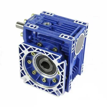
90 degree KM Series Helical Hypoid Gear reducer price mini bevel gearbox worm drive shaft gear box
1.KM series Helical-hypoid Gearbox’s Characteristics
KM series helical-hypoid gearbox is a new-generation of product developed by Aokman. With a compromise of advanced technology both at home and abroad, its main features are as follows:
(1) Driven by hypoid gears, which has big ratios.
(2) Large output torque, high efficiency, energy saving and environmental protection.
(3) High-quality aluminum alloy housing, and light in weight and non-rusting.
(4) Smooth in running and low in noise, and can work long time in dreadful conditions.
(5) Good-looking in appearance, durable in service life and small in volume.
(6) Suitable for all round installation, wide application and easy use.
(7) The mounting dimension of KM series helical-hypoid gearbox are compatible with RV series worm gearbox.
(8) Modular and multi-structure can meet the demands of various conditions.
Detailed Photos
2. KM series Helical-hypoid Gearbox’s Main Materials
(1) Housing: die-cast aluminum alloy (frame size 27 to 57)
(2) Gear wheel: 20CrMnTiH1 carbonizing & quenching heat treatment make the hardness of gears surface be up to 56-62 HRC, and be retained carburization layers thickness between 0.3 and 0.5mm after precise grinding.
3. KM series Helical-hypoid Gearbox’s Surface Painting
Aluminum alloy housing:
(1) Shot blasting and special antiseptic treatment on the aluminum alloy surface.
(2) After phosphating, spray the RAL9571 silver white paint.4.Gearbox Parameters
Product Parameters
| Models | Stage | Nominal Ratio | Output Speed (n2)* | Max. Torque | Input Shaft Dia. | Output Hole Dia. | Output Shaft Dia. |
| KM050 | 3 Stage | 50~300 | 4.8~27 | 130N.m | Φ11 | Φ20, Φ24 | Φ25 |
| 2 Stage | 7.5~60 | 24~181 | 130N.m | Φ11 | |||
| KM063 | 3 Stage | 50~300 | 4.6~27 | 200N.m | Φ11 | Φ25, Φ28 | Φ25 |
| 2 Stage | 7.5~60 | 23~184 | 200N.m | Φ14 | |||
| KM075 | 3 Stage | 50~300 | 4.7~28 | 350N.m | Φ14 | Φ28, Φ30, Φ35 | Φ28 |
| 2 Stage | 7.5~60 | 24~187 | 350N.m | Φ16 | |||
| KM090 | 3 Stage | 50~300 | 4.7~28 | 500N.m | Φ14 | Φ35, Φ38 | Φ35 |
| 2 Stage | 7.5~60 | 24~187 | 500N.m | Φ19 | |||
| KM110 | 3 Stage | 50~300 | 4.7~27 | 750N.m | Φ19 | Φ40, Φ42 | Φ42 |
| 2 Stage | 7.5~60 | 24~187 | 750N.m | Φ24 |
Packaging & Shipping
Company Profile
Our Advantages
After Sales Service
| Pre-sale services | 1. Select equipment model. |
| 2.Design and manufacture products according to clients’ special requirement. | |
| 3.Train technical personal for clients | |
| Services during selling | 1.Pre-check and accept products ahead of delivery. |
| 2. Help clients to draft solving plans. | |
| After-sale services | 1.Assist clients to prepare for the first construction scheme. |
| 2. Train the first-line operators. | |
| 3.Take initiative to eliminate the trouble rapidly. | |
| 4. Provide technical exchanging. |
FAQ
1.Q:What kinds of gearbox can you produce for us?
A:Main products of our company: UDL series speed variator,RV series worm gear reducer, ATA series shaft mounted gearbox, X,B series gear reducer,
P series planetary gearbox and R, S, K, and F series helical-tooth reducer, more
than 1 hundred models and thousands of specifications
2.Q:Can you make as per custom drawing?
A: Yes, we offer customized service for customers.
3.Q:What is your terms of payment ?
A: 30% Advance payment by T/T after signing the contract.70% before delivery
4.Q:What is your MOQ?
A: 1 Set
If you have any demand for our products please feel free to contact me.
| Application: | Motor, Machinery |
|---|---|
| Function: | Speed Changing, Speed Reduction |
| Layout: | Orthogonal |
| Hardness: | Hardened Tooth Surface |
| Installation: | Industry |
| Step: | Double or Three-Step |
| Customization: |
Available
| Customized Request |
|---|

Can a Worm Gearbox Be Used in Heavy-Duty Machinery?
Yes, a worm gearbox can be used in heavy-duty machinery and is often chosen for such applications due to its inherent characteristics and advantages:
- High Torque Transmission: Worm gearboxes are known for their ability to transmit high torque loads, making them suitable for heavy-duty machinery that requires significant power transmission.
- Load Distribution: The design of worm gears provides robust load distribution and excellent contact between the worm and worm wheel teeth. This enhances their load-carrying capacity, making them capable of handling heavy loads without premature wear or failure.
- Compact Design: Worm gearboxes are compact and offer high reduction ratios in a single stage. This allows for the reduction of high input speeds to lower output speeds, often required in heavy-duty machinery.
- Overload Protection: Worm gears have a natural self-locking feature, which means the gear cannot be easily back-driven by external forces. This feature provides inherent overload protection, preventing damage to the gearbox and machinery in cases of sudden load spikes.
- Smooth Operation: Worm gearboxes offer smooth and steady operation, which is crucial for heavy-duty machinery where precision and controlled movement are essential.
However, when considering the use of a worm gearbox in heavy-duty applications, it’s important to ensure proper engineering and sizing. The design should account for factors such as load, speed, duty cycle, lubrication, and temperature to ensure optimal performance and longevity.
Overall, worm gearboxes are well-suited for heavy-duty machinery across various industries, including mining, construction, manufacturing, and more.

Materials Used for Worm Gears
Worm gears are manufactured using a variety of materials to meet different application requirements. Some commonly used materials for worm gears include:
- Steel: Steel is a popular choice for worm gears due to its strength, durability, and wear resistance. It can handle heavy loads and is often used in industrial applications.
- Bronze: Bronze offers good lubricity and is commonly used for the worm gear (worm) component. It provides effective wear resistance and works well in applications where quiet operation is essential.
- Cast Iron: Cast iron is known for its high strength and durability. It’s often used for worm gears in applications where shock loads or heavy-duty conditions are expected.
- Aluminum: Aluminum worm gears are lightweight and corrosion-resistant, making them suitable for applications where weight reduction is important.
- Plastic: Some worm gears are made from plastic materials such as nylon or acetal. These materials are often chosen for their self-lubricating properties and quiet operation.
- Composite Materials: Composite materials can offer a combination of properties, such as lightweight construction and corrosion resistance. They can be suitable for specific applications.
The choice of material depends on factors such as the application’s load, speed, operating environment, and required performance characteristics. It’s important to consider these factors when selecting the appropriate material for worm gears to ensure optimal performance and longevity.

How to Select the Right Worm Gearbox for Your Application
Selecting the right worm gearbox for your application involves careful consideration of various factors:
- Load Requirements: Determine the torque and load requirements of your application to ensure the selected gearbox can handle the load without compromising performance.
- Speed Reduction: Calculate the required gear reduction ratio to achieve the desired output speed. Worm gearboxes are known for high reduction ratios.
- Efficiency: Consider the gearbox’s efficiency, as worm gearboxes typically have lower efficiency due to the sliding action. Evaluate whether the efficiency meets your application’s needs.
- Space Constraints: Assess the available space for the gearbox. Worm gearboxes have a compact design, making them suitable for applications with limited space.
- Mounting Options: Determine the mounting orientation and configuration that best suits your application.
- Operating Environment: Consider factors such as temperature, humidity, and exposure to contaminants. Choose a gearbox with appropriate seals and materials to withstand the environment.
- Backlash: Evaluate the acceptable level of backlash in your application. Worm gearboxes may exhibit more backlash compared to other gear types.
- Self-Locking: If self-locking capability is required, confirm that the selected gearbox can prevent reverse motion without the need for external braking mechanisms.
- Maintenance: Consider the maintenance requirements of the gearbox. Some worm gearboxes require periodic lubrication and maintenance to ensure proper functioning.
- Cost: Balance the features and performance of the gearbox with the overall cost to ensure it aligns with your budget.
Consult with gearbox manufacturers or experts to get recommendations tailored to your specific application. Testing and simulations can also help validate the suitability of a particular gearbox for your needs.


editor by CX 2023-09-13
China Standard Wpda Worm Shaft Reducer Wp Series Worm Gear Reduction Gearbox with Good quality
Product Description
Product Parameters
|
Model Ratio |
10 |
15 |
20 |
25 |
30 |
40 |
50 |
60 |
|
40 |
0.4 |
0.33 |
0.26 |
0.24 |
0.22 |
0.16 |
0.14 |
o.12 |
|
50 |
0.65 |
0.52 |
0.40 |
0.37 |
0.34 |
0.27 |
0.24 |
0.20 |
|
60 |
1.00 |
0.82 |
0.65 |
0.59 |
0.54 |
0.45 |
0.40 |
0.32 |
|
70 |
1.60 |
1.35 |
1.10 |
0.96 |
0.82 |
0.67 |
0.61 |
0.52 |
|
80 |
2.20 |
1.78 |
1.36 |
1.28 |
1.20 |
0.90 |
0.80 |
0.75 |
|
100 |
3.60 |
3.10 |
2.60 |
2.35 |
2.10 |
1.68 |
1.30 |
1.00 |
|
120 |
5.20 |
4.35 |
3.50 |
3.25 |
3.00 |
2.20 |
1.90 |
1.50 |
|
135 |
9.75 |
7.85 |
6.00 |
5.50 |
5.00 |
3.69 |
2.89 |
2.30 |
|
147 |
10.71 |
8.43 |
6.18 |
5.71 |
5.23 |
3.84 |
3.09 |
2.52 |
|
155 |
12.80 |
9.90 |
7.00 |
6.53 |
6.00 |
4.40 |
3.61 |
3.00 |
|
175 |
17.30 |
13.60 |
10.00 |
9.13 |
8.30 |
6.18 |
4.85 |
4.07 |
|
200 |
22.60 |
18.20 |
13.86 |
12.75 |
11.67 |
8.78 |
6.71 |
5.58 |
|
250 |
33.20 |
27.40 |
21.60 |
20.00 |
18.43 |
14.00 |
10.43 |
8.62 |
Product Description
Product Description
(1)Worm gear reducer is a power transmission mechanism, the use of gear speed converter, the motor (motor) the number of rotation to slow down to the number of rotation, and get a larger torque mechanism. At present, the application of speed reducer is widely used in the mechanism of transmitting power and motion.
(2)In all kinds of mechanical transmission system can see traces of it, from the transport ships, automobiles, motorcycles, construction heavy machinery, industrial machinery processing equipment and automated production equipment, to the common daily life appliances, clocks and watches, and so forth. Its application from the transmission of large power, to a small load, the precision of the angle of transmission can be seen in the application, and in industrial applications, the reducer has a reduction and increase the torque function. So it is widely used in speed and torque conversion equipmen
The role of main reducer:
1, reduce speed and increase the output torque, torque output ratio of motor output by the deceleration ratio, but should pay attention to not exceed the speed reducer rated torque.
2, deceleration while reducing the load inertia, inertia is reduced to the square of the reduction ratio. We can look at the General Motors has a value of inertia.
Detailed Photos
Parameter
Certifications
| Application: | Electric Cars, Motorcycle, Agricultural Machinery, Car, Power Transmission |
|---|---|
| Layout: | Three-Ring |
| Hardness: | Hardened Tooth Surface |
| Installation: | Torque Arm Type |
| Type: | Worm Gear Box |
| Input Speed: | 1440rpm |
| Samples: |
US$ 50/Piece
1 Piece(Min.Order) | |
|---|
Common Problems and Troubleshooting for Worm Gearboxes
Worm gearboxes, like any mechanical component, can experience various issues over time. Here are some common problems that may arise and possible troubleshooting steps:
- Overheating: Overheating can occur due to factors such as inadequate lubrication, excessive loads, or high operating temperatures. Check lubrication levels, ensure proper ventilation, and reduce loads if necessary.
- Noise and Vibration: Excessive noise and vibration may result from misalignment, worn gears, or improper meshing. Check for misalignment, inspect gear teeth for wear, and ensure proper gear meshing.
- Leakage: Oil leakage can be caused by damaged seals or gaskets. Inspect seals and gaskets, and replace them if necessary.
- Reduced Efficiency: Efficiency loss can occur due to friction, wear, or misalignment. Regularly monitor gearbox performance, ensure proper lubrication, and address any wear or misalignment issues.
- Backlash: Excessive backlash can affect precision and accuracy. Adjust gear meshing and reduce backlash to improve performance.
- Seizure or Binding: Seizure or binding can result from inadequate lubrication, debris, or misalignment. Clean the gearbox, ensure proper lubrication, and address misalignment issues.
- Worn Gears: Worn gear teeth can lead to poor performance. Regularly inspect gears for signs of wear, and replace worn gears as needed.
- Seal Wear: Seals can wear over time, leading to leakage and contamination. Inspect seals regularly and replace them if necessary.
If you encounter any of these problems, it’s important to address them promptly to prevent further damage and maintain the performance of your worm gearbox. Regular maintenance, proper lubrication, and addressing issues early can help extend the lifespan and reliability of the gearbox.

How to Calculate the Efficiency of a Worm Gearbox
Calculating the efficiency of a worm gearbox involves determining the ratio of output power to input power. Efficiency is a measure of how well the gearbox converts input power into useful output power without losses. Here’s how to calculate it:
- Step 1: Measure Input Power: Measure the input power (Pin) using a power meter or other suitable measuring equipment.
- Step 2: Measure Output Power: Measure the output power (Pout) that the gearbox is delivering to the load.
- Step 3: Calculate Efficiency: Calculate the efficiency (η) using the formula: Efficiency (η) = (Output Power / Input Power) * 100%
For example, if the input power is 1000 watts and the output power is 850 watts, the efficiency would be (850 / 1000) * 100% = 85%.
It’s important to note that efficiencies can vary based on factors such as gear design, lubrication, wear, and load conditions. The calculated efficiency provides insight into how effectively the gearbox is converting power, but it’s always a good practice to refer to manufacturer specifications for gearbox efficiency ratings.

Preventing Backlash in a Worm Gearbox
Backlash in a worm gearbox can lead to reduced accuracy, positioning errors, and decreased overall efficiency. Here are steps to prevent or minimize backlash:
- High-Quality Components: Use high-quality worm gears and worm wheels with tight manufacturing tolerances. Precision components will help reduce backlash.
- Proper Meshing: Ensure the worm gear and worm wheel are properly aligned and meshed. Improper meshing can lead to increased backlash.
- Preload: Applying a small amount of preload to the worm gear can help reduce backlash. However, excessive preload can increase friction and wear.
- Anti-Backlash Mechanisms: Consider using anti-backlash mechanisms, such as spring-loaded systems or adjustable shims, to compensate for any inherent backlash.
- Lubrication: Proper lubrication can reduce friction and play a role in minimizing backlash. Use a lubricant that provides good film strength and reduces wear.
- Maintenance: Regularly inspect and maintain the gearbox to identify and address any changes in backlash over time.
It’s important to strike a balance between reducing backlash and maintaining smooth operation. Consulting with gearbox experts and following manufacturer guidelines will help you optimize your worm gearbox’s performance while minimizing backlash.
editor by CX 2023-09-13
China Professional Nmrv/Nrv Nmrv110 Worm Gear Speed Reduction Reducer Gearbox with high quality
Product Description
NMRV REDUCTION WORM GEARBOX
The NMRV 110 angular worm gear motor is designed to increase torque while reducing rotational speed. The drive is equipped with a single-stage gearbox and an electric motor with a power of 0.55 – 7.5 kW. The torque on the output shaft is 163 – 767 N * m. Gear Ratio Range: 7.5 – 100.
The NMRV 110 unit has the same mounting dimensions as the SITI MU105 and Varvel SRT 110 gearmotors, so it can be used to replace them.
Materials parts:
Body – iron, flanges – iron, worm – steel CHINAMFG worm wheel – bronze.
Type of lubricant: synthetic ISO VG 220.
Weight: 35 kg.
Type designation scheme
NMRV – 110 – 40 – 35 – 1.5 – B6
- NMRV – worm gear motor
- 110 – size (center distance, mm)
- 40 – gear ratio
- 35 – output shaft rotation speed, rpm
- 1,5 – electric motor power, kW
- B6 – mounting position
NMRV 110 gearbox performance
| i | n 1 = 2800 rpm | n 1 = 1400 rpm | n 1 = 900, rpm | |||||||||
| n 2 , rpm |
T 2M , N * m |
P kw |
RD % |
n 2 , rpm |
T 2M , N * m |
P kw |
RD % |
n 2 , rpm |
T 2M , N * m |
P kw |
RD % |
|
| 7.5 | 373 | 391 | 16.60 | 92 | 187 | 532 | 11.60 | 90 | 120 | 637 | 9.10 | 88 |
| 10 | 280 | 424 | 13.50 | 92 | 140 | 571 | 9.30 | 90 | 90 | 672 | 7.20 | 87 |
| 15 | 187 | 423 | 9.30 | 89 | 93 | 565 | 6.40 | 86 | 60 | 669 | 5.00 | 84 |
| 20 | 140 | 498 | 8.30 | 88 | 70 | 649 | 5.60 | 85 | 45 | 748 | 4.30 | 82 |
| 25 | 112 | 453 | 5.90 | 90 | 56 | 580 | 4.00 | 85 | 36 | 674 | 3.10 | 82 |
| 30 | 93 | 349 | 4.00 | 85 | 47 | 553 | 3.40 | 80 | 30 | 663 | 2.70 | 77 |
| 40 | 70 | 554 | 4.90 | 83 | 35 | 681 | 3.20 | 78 | 23 | 809 | 2.60 | 75 |
| 50 | 56 | 531 | 3.80 | 82 | 28 | 657 | 2.50 | 77 | 18 | 746 | 1.90 | 74 |
| 60 | 47 | 428 | 2.70 | 78 | 23 | 546 | 1.80 | 73 | 15 | 615 | 1.40 | 69 |
| 80 | 35 | 445 | 2.20 | 74 | 18 | 549 | 1.50 | 68 | 11 | 640 | 1.10 | 67 |
| 100 | 28 | 394 | 1.70 | 68 | 14 | 473 | 1.10 | 63 | 9 | 557 | 0.89 | 59 |
- n1 – rotational speed el. engine;
- n2 – revolutions on the output shaft;
- T 2M – torque on the output shaft;
- P is the maximum allowable engine power;
- RD – efficiency
GEARBOX FEATURE
| 1.Good quality,long life time,low noise. |
| 2.Compact,convenient. |
| 3.High efficiency,big torque. |
Overall and mounting dimensions NMRV 110
NMRV110 gear motor has a wide range of gear ratios.
Gear ratios: 7.5, 10, 15, 20, 25, 30, 40, 50, 60, 80, 100 .
Output flange to NMRV 110 gearbox
Geared NMRV110 can be supplied with unilateral or bilateral output shaft.
The gearbox comes standard with a hollow output shaft
A torque arm is an additional option to the gearbox.
| Model | NMRV SERIES |
| Single Stage | RV25-RV150 |
| Ratio | 7.5-100 |
| Input Power | 0.06KW-15KW |
| Output Speed | 14-280rpm |
| Output Torque | 5-1800Nm |
| Core parts | worm wheel,worm shaft |
| Core parts material | worm shaft:20 Cr Mn Ti,worm wheel:Nodular cast iron interal,9-4 copper external |
| Lubrication | RV30-90:synthetic oil, RV110-150:GN460-W mineral oil |
| Bearings | C&U |
| Application: | Motor, Motorcycle, Machinery, Agricultural Machinery, Industry |
|---|---|
| Hardness: | Hardened |
| Installation: | Any Angle |
| Gear Shape: | Worm Gear |
| Step: | Single-Step |
| Type: | Worm and Wormwheel |
| Samples: |
US$ 20/Piece
1 Piece(Min.Order) | |
|---|
| Customization: |
Available
| Customized Request |
|---|
Maintenance Tips for Prolonging the Life of a Worm Gearbox
Proper maintenance is essential to ensure the longevity and reliable performance of a worm gearbox. Here are some maintenance tips to consider:
- Lubrication: Regularly check and replenish the lubricant in the gearbox. Use the recommended lubricant type and quantity specified by the manufacturer.
- Lubrication Schedule: Follow a lubrication schedule based on the operating conditions and manufacturer recommendations. Regular lubrication prevents friction, reduces wear, and dissipates heat.
- Temperature Monitoring: Keep an eye on the operating temperature of the gearbox. Excessive heat can degrade the lubricant and damage components.
- Cleanliness: Keep the gearbox and surrounding area clean from debris and contaminants. Regularly inspect and clean the gearbox exterior.
- Seal Inspection: Check for any leaks or damage to seals and gaskets. Replace them promptly to prevent lubricant leaks and contamination.
- Alignment: Ensure proper alignment between the worm and worm wheel. Misalignment can lead to increased wear and reduced efficiency.
- Torque Monitoring: Monitor the torque levels during operation. Excessive torque can cause overloading and premature wear.
- Regular Inspections: Periodically inspect all components for signs of wear, damage, or unusual noise. Replace worn or damaged parts promptly.
- Proper Usage: Operate the gearbox within its specified limits, including load, speed, and temperature. Avoid overloading or sudden changes in operating conditions.
- Expert Maintenance: If major maintenance or repairs are needed, consult the manufacturer’s guidelines or seek the assistance of qualified technicians.
By following these maintenance tips and adhering to the manufacturer’s recommendations, you can extend the lifespan of your worm gearbox and ensure its optimal performance over time.
How to Calculate the Efficiency of a Worm Gearbox
Calculating the efficiency of a worm gearbox involves determining the ratio of output power to input power. Efficiency is a measure of how well the gearbox converts input power into useful output power without losses. Here’s how to calculate it:
- Step 1: Measure Input Power: Measure the input power (Pin) using a power meter or other suitable measuring equipment.
- Step 2: Measure Output Power: Measure the output power (Pout) that the gearbox is delivering to the load.
- Step 3: Calculate Efficiency: Calculate the efficiency (η) using the formula: Efficiency (η) = (Output Power / Input Power) * 100%
For example, if the input power is 1000 watts and the output power is 850 watts, the efficiency would be (850 / 1000) * 100% = 85%.
It’s important to note that efficiencies can vary based on factors such as gear design, lubrication, wear, and load conditions. The calculated efficiency provides insight into how effectively the gearbox is converting power, but it’s always a good practice to refer to manufacturer specifications for gearbox efficiency ratings.
Preventing Backlash in a Worm Gearbox
Backlash in a worm gearbox can lead to reduced accuracy, positioning errors, and decreased overall efficiency. Here are steps to prevent or minimize backlash:
- High-Quality Components: Use high-quality worm gears and worm wheels with tight manufacturing tolerances. Precision components will help reduce backlash.
- Proper Meshing: Ensure the worm gear and worm wheel are properly aligned and meshed. Improper meshing can lead to increased backlash.
- Preload: Applying a small amount of preload to the worm gear can help reduce backlash. However, excessive preload can increase friction and wear.
- Anti-Backlash Mechanisms: Consider using anti-backlash mechanisms, such as spring-loaded systems or adjustable shims, to compensate for any inherent backlash.
- Lubrication: Proper lubrication can reduce friction and play a role in minimizing backlash. Use a lubricant that provides good film strength and reduces wear.
- Maintenance: Regularly inspect and maintain the gearbox to identify and address any changes in backlash over time.
It’s important to strike a balance between reducing backlash and maintaining smooth operation. Consulting with gearbox experts and following manufacturer guidelines will help you optimize your worm gearbox’s performance while minimizing backlash.
editor by CX 2023-09-13
China Professional Nmrv/Nrv Nmrv040 Worm Gear Speed Reduction Reducer Gearbox cvt gearbox
Product Description
NMRV REDUCTION WORM GEARBOX
The NMRV 040 worm gear motor is characterized by a wide range of gear ratios (5 – 80), a compact aluminum alloy housing, and ease of installation and maintenance. The unit is equipped with an engine power of 0.09 – 0.55 kW. Output shaft rotation frequency: 900 – 2800 rpm.
The NMRV 040 motor gearbox has similar mounting dimensions with the Siti MU40, STM UMI 40, Varvel SRT 40 drives and can be used to replace them.
Parts materials:
Case – aluminum, flanges – aluminum, worm – steel, worm wheel CHINAMFG – bronze.
Type of lubricant: synthetic ISO VG 320.
Weight: 2.3 kg.
Type designation scheme
NMRV – 040 – 80 – 17.5 – 0.12 – B3
- NMRV – worm gear motor
- 040 – size (center distance, mm)
- 80 – gear ratio
- 17.5 – output shaft rotation speed, rpm
- 0,12 – electric motor power, kW
- B3 – mounting position
NMRV 040 gearbox performance
| I |
n 1 = 2800 rpm | n 1 = 1400 rpm | n 1 = 900, rpm | |||||||||
| n 2 , rpm |
T 2M , N * m |
P kw |
RD % |
n 2 , rpm |
T 2M , N * m |
P kw |
RD % |
n 2 , rpm |
T 2M , N * m |
P kw |
RD % |
|
| 5 | 560 | 24 | 1.50 | 87 | 280 | 36 | 1.10 | 86 | 180 | 41 | 0.80 | 84 |
| 7.5 | 373 | 29 | 1.30 | 88 | 187 | 41 | 0.93 | 86 | 120 | 49 | 0.73 | 84 |
| 10 | 280 | 32 | 1.10 | 86 | 140 | 44 | 0.76 | 84 | 90 | 50 | 0.58 | 82 |
| 15 | 187 | 34 | 0.78 | 84 | 93 | 44 | 0.53 | 81 | 60 | 52 | 0.41 | 79 |
| 20 | 140 | 31 | 0.56 | 82 | 70 | 40 | 0.37 | 79 | 45 | 47 | 0.29 | 76 |
| 25 | 112 | 34 | 0.50 | 79 | 56 | 43 | 0.34 | 74 | 36 | 49 | 0.26 | 71 |
| 30 | 93 | 33 | 0.44 | 73 | 47 | 38 | 0.27 | 68 | 30 | 43 | 0.21 | 65 |
| 40 | 70 | 35 | 0.36 | 72 | 35 | 44 | 0.24 | 67 | 23 | 52 | 0.19 | 64 |
| 50 | 56 | 32 | 0.29 | 65 | 28 | 41 | 0.20 | 60 | 18 | 48 | 0.16 | 57 |
| 60 | 47 | 29 | 0.24 | 59 | 23 | 38 | 0.17 | 54 | 15 | 41 | 0.13 | 50 |
| 80 | 35 | 23 | 0.15 | 56 | 18 | 31 | 0.11 | 51 | 11 | 37 | 0.09 | 49 |
| 100 | 28 | 24 | 0.13 | 53 | 14 | 29 | 0.09 | 48 | 9 | 33 | 0.07 | 44 |
- n1 – rotational speed el. engine;
- n2 – revolutions on the output shaft;
- T 2M – torque on the output shaft;
- P is the maximum allowable engine power;
- RD – efficiency
GEARBOX FEATURE
| 1.Good quality,long life time,low noise. |
| 3.High efficiency,big torque. |
Overall and mounting dimensions NMRV 040
NMRV040 gear motor has a wide range of gear ratios.
Gear ratios: 5, 7.5, 10, 15, 20, 25, 30, 40, 50, 60, 80, 100 .
Output flange to NMRV 040 gearbox
Geared NMRV040 can be supplied with unilateral or bilateral output shaft.
The gearbox comes standard with a hollow output shaft
A torque arm is an additional option to the gearbox.
| Model | NMRV SERIES |
| Single Stage | RV25-RV150 |
| Ratio | 7.5-100 |
| Input Power | 0.06KW-15KW |
| Output Speed | 14-280rpm |
| Output Torque | 5-1800Nm |
| Core parts | worm wheel,worm shaft |
| Core parts material | worm shaft:20 Cr Mn Ti,worm wheel:Nodular cast iron interal,9-4 copper external |
| Lubrication | RV30-90:synthetic oil, RV110-150:GN460-W mineral oil |
| Bearings | C&U |
| Application: | Motor, Motorcycle, Machinery, Agricultural Machinery, Industry |
|---|---|
| Hardness: | Hardened |
| Installation: | Any Angle |
| Gear Shape: | Worm Gear |
| Step: | Single-Step |
| Type: | Worm and Wormwheel |
| Samples: |
US$ 20/Piece
1 Piece(Min.Order) | |
|---|
| Customization: |
Available
| Customized Request |
|---|

Calculating Gear Ratio in a Worm Reducer
The gear ratio in a worm reducer is determined by the number of teeth on the worm wheel (also known as the worm gear) and the number of threads on the worm shaft. The gear ratio formula for a worm reducer is:
Gear Ratio = Number of Teeth on Worm Wheel / Number of Threads on Worm Shaft
For example, if the worm wheel has 60 teeth and the worm shaft has a single thread, the gear ratio would be 60:1.
It’s important to note that worm reducers have an inherent self-locking property due to the angle of the worm threads. As a result, the gear ratio also affects the mechanical advantage and the system’s ability to resist backdriving.
When calculating the gear ratio, ensure that the worm reducer is properly designed and that the gear ratio aligns with the desired mechanical characteristics for your application. Additionally, consider factors such as efficiency, load capacity, and speed limitations when selecting a gear ratio for a worm reducer.

Worm Gearboxes in Conveyor Systems: Benefits and Considerations
Worm gearboxes play a crucial role in conveyor systems, offering several benefits and considerations for their effective integration:
- Space Efficiency: Worm gearboxes have a compact design, making them suitable for applications with limited space, such as conveyor systems.
- High Reduction Ratios: Worm gearboxes can achieve high reduction ratios in a single stage, allowing for slower conveyor speeds without sacrificing torque.
- Self-Locking: Worm gearboxes have inherent self-locking properties, preventing the conveyor from moving when the motor is not actively driving it.
- Directional Control: Worm gearboxes facilitate directional control, enabling the conveyor to move forward or reverse as needed.
- Low Noise: Worm gearboxes often produce lower noise levels compared to other gearbox types, contributing to quieter conveyor operation.
However, there are also considerations to keep in mind when using worm gearboxes in conveyor systems:
- Efficiency: Worm gearboxes may have lower mechanical efficiency compared to some other gearbox types, leading to energy losses.
- Heat Generation: Worm gearboxes can generate more heat due to sliding contact between the worm and gear, necessitating proper cooling mechanisms.
- Lubrication: Proper lubrication is critical to prevent wear and ensure efficient operation. Regular maintenance is required to monitor lubrication levels.
- Load and Speed: Worm gearboxes are well-suited for applications with high torque and low to moderate speed requirements. They may not be optimal for high-speed conveyors.
Before integrating a worm gearbox into a conveyor system, it’s important to carefully consider the specific requirements of the application, including load, speed, space constraints, and efficiency needs. Consulting with gearbox experts and manufacturers can help ensure the right choice for the conveyor’s performance and longevity.
Types of Worm Gear Configurations and Their Uses
Worm gear configurations vary based on the arrangement of the worm and the gear it engages with. Here are common types and their applications:
- Single Enveloping Worm Gear: This configuration offers high torque transmission and efficiency. It’s used in heavy-duty applications like mining equipment and industrial machinery.
- Double Enveloping Worm Gear: With increased contact area, this type provides higher load capacity and improved efficiency. It’s used in aerospace applications, robotics, and precision machinery.
- Non-Throated Worm Gear: This type has a cylindrical worm without a throat. It’s suitable for applications requiring precise motion control, such as CNC machines and robotics.
- Throated Worm Gear: Featuring a throat in the worm, this configuration offers smooth engagement and higher load capacity. It’s used in conveyors, elevators, and automotive applications.
- Non-Modular Worm Gear: In this design, the worm and gear are a matched set, resulting in better meshing and efficiency. It’s utilized in various industries where customization is essential.
- Modular Worm Gear: This type allows interchangeability of worm and gear components, providing flexibility in design and maintenance. It’s commonly used in conveyors, mixers, and material handling systems.
Selecting the appropriate worm gear configuration depends on factors such as load capacity, efficiency, precision, and application requirements. Consulting gearbox experts can help determine the best configuration for your specific needs.
editor by CX 2023-09-13
China factory 318 Series Inline Planetary Gearbox Gear Reducer Replacement of CZPT gearbox engine
Product Description
318 Series inline Planetary Gearbox Gear Reducer 318L1 318L2 318L3 318L48 318R4 replacement of bonfiglioli
Product Description
The 300L series and 300R series planetary gearboxes can be interchangeable with the following models of Trasmital Bonfiglioli
| 300L 1 | 300L 2 | 300L 3 | 300L 4 | 300R2 | 300R3 | 300R4 |
| 301L 1 | 301L 2 | 301L 3 | 301L 4 | 301R2 | 301R3 | 301R4 |
| 303L 1 | 303L 2 | 303L 3 | 303L 4 | 303R2 | 303R3 | 303R4 |
| 305L 1 | 305L 2 | 305L 3 | 305L 4 | 305R2 | 305R3 | 305R4 |
| 306L 1 | 306L 2 | 306L 3 | 306L 4 | 306R2 | 306R3 | 306R4 |
| 307L 1 | 307L 2 | 307L 3 | 307L 4 | 307R2 | 307R3 | 307R4 |
| 309L 1 | 309L 2 | 309L 3 | 309L 4 | 309R2 | 309R3 | 309R4 |
| 310L 1 | 310L 2 | 310L 3 | 310L 4 | 310R2 | 310R3 | 310R4 |
| 311L 1 | 311L 2 | 311L 3 | 311L 4 | 311R2 | 311R3 | 311R4 |
| 313L 1 | 313L 2 | 313L 3 | 313L 4 | 313R2 | 313R3 | 313R4 |
| 315L 1 | 315L 2 | 315L 3 | 315L 4 | 315R3 | 315R4 | |
| 316L 1 | 316L 2 | 316L 3 | 316L 4 | 316R3 | 316R4 | |
| 317L 1 | 317L 2 | 317L 3 | 317L 4 | 317R3 | 317R4 | |
| 318L 1 | 318L 2 | 318L 3 | 318L 4 | 318R4 | ||
| 319L 1 | 319L 2 | 319L 3 | 319L 4 | 319R4 | ||
| 321L 1 | 321L 2 | 321L 3 | 321L 4 | 321R4 |
-
Torque range
1,000 … 1,100,000 Nm (8,850 … 9,735,820 in-lb) -
Gear ratios
3.4 … 5,000 -
Transmissible Mechanical Power
up to 1,050 kW -
Brake options
Hydraulic brake
Hydraulically released parking brake on request
Electric brake
DC and AC type -
Output
Foot and flange mounted
Output shaft: CHINAMFG with key, splined, splined hollow, hollow with shrink disc -
Input
Flanged axial piston hydraulic motors
Hydraulic orbit motors
IEC and Nema motor adapters
Solid input shaft -
Applicable motors
Piston hydraulic motors
Hydraulic orbit motors
Electric motors IEC
Key Features
1. Torque range: 1000-450.000 Nm
2. Transmissible mechanical power: up to 540 kW
3. Gear ratios: 3.4-9.000
4. Gear unit versions: in line
5. Output configurations:
1) Foot and flange mounted
2) Output shaft: CHINAMFG with key, splined, splined hollow
3) Hollow with shrink disc
6. Input configurations:
1) Flanged axial piston hydraulic motors
2) Hydraulic orbit motors
3) IEC and Nema motor adaptors
4) CHINAMFG input shaft
7. Hydraulic brake: hydraulically released parking brake
8. Electric brake: DC and AC type
Application
Our factory
Related Products
For more reducers and mechanical accessories, please click here to view
| Application: | Motor, Electric Cars, Motorcycle, Machinery, Marine, Toy, Agricultural Machinery, Car |
|---|---|
| Function: | Distribution Power, Speed Changing, Speed Reduction |
| Layout: | Wrom |
| Hardness: | Hardened Tooth Surface |
| Installation: | Planetary |
| Step: | Planetary |

Are there any disadvantages or limitations to using gear reducer systems?
While gear reducer systems offer numerous advantages, they also come with certain disadvantages and limitations that should be considered during the selection and implementation process:
1. Size and Weight: Gear reducers can be bulky and heavy, especially for applications requiring high gear ratios. This can impact the overall size and weight of the machinery or equipment, which may be a concern in space-constrained environments.
2. Efficiency Loss: Despite their high efficiency, gear reducers can experience energy losses due to friction between gear teeth and other components. This can lead to a reduction in overall system efficiency, particularly in cases where multiple gear stages are used.
3. Cost: The design, manufacturing, and assembly of gear reducers can involve complex processes and precision machining, which can contribute to higher initial costs compared to other power transmission solutions.
4. Maintenance: Gear reducer systems require regular maintenance, including lubrication, inspection, and potential gear replacement over time. Maintenance activities can lead to downtime and associated costs in industrial settings.
5. Noise and Vibration: Gear reducers can generate noise and vibrations, especially at high speeds or when operating under heavy loads. Additional measures may be needed to mitigate noise and vibration issues.
6. Limited Gear Ratios: While gear reducers offer a wide range of gear ratios, there may be limitations in achieving extremely high or low ratios in certain designs.
7. Temperature Sensitivity: Extreme temperatures can affect the performance of gear reducer systems, particularly if inadequate lubrication or cooling is provided.
8. Shock Loads: While gear reducers are designed to handle shock loads to some extent, severe shock loads or abrupt changes in torque can still lead to potential damage or premature wear.
Despite these limitations, gear reducer systems remain widely used and versatile components in various industries, and their disadvantages can often be mitigated through proper design, selection, and maintenance practices.

What factors should be considered when selecting the right gear reducer?
Choosing the appropriate gear reducer involves considering several crucial factors to ensure optimal performance and efficiency for your specific application:
- 1. Torque and Power Requirements: Determine the amount of torque and power your machinery needs for its operation.
- 2. Speed Ratio: Calculate the required speed reduction or increase to match the input and output speeds.
- 3. Gear Type: Select the appropriate gear type (helical, bevel, worm, planetary, etc.) based on your application’s torque, precision, and efficiency requirements.
- 4. Mounting Options: Consider the available space and the mounting configuration that suits your machinery.
- 5. Environmental Conditions: Evaluate factors such as temperature, humidity, dust, and corrosive elements that may impact the gear reducer’s performance.
- 6. Efficiency: Assess the gear reducer’s efficiency to minimize power losses and improve overall system performance.
- 7. Backlash: Consider the acceptable level of backlash or play between gear teeth, which can affect precision.
- 8. Maintenance Requirements: Determine the maintenance intervals and procedures necessary for reliable operation.
- 9. Noise and Vibration: Evaluate noise and vibration levels to ensure they meet your machinery’s requirements.
- 10. Cost: Compare the initial cost and long-term value of different gear reducer options.
By carefully assessing these factors and consulting with gear reducer manufacturers, engineers and industry professionals can make informed decisions to select the right gear reducer for their specific application, optimizing performance, longevity, and cost-effectiveness.

Function of Gear Reducers in Mechanical Systems
A gear reducer, also known as a gear reduction unit or gearbox, is a mechanical device designed to reduce the speed of an input shaft while increasing its torque output. It accomplishes this through the use of a set of interlocking gears with different sizes.
The primary function of a gear reducer in mechanical systems is to:
- Speed Reduction: The gear reducer takes the high-speed rotation of the input shaft and transmits it to the output shaft through a set of gears. The gears are configured in such a way that the output gear has a larger diameter than the input gear. As a result, the output shaft rotates at a lower speed than the input shaft, but with increased torque.
- Torque Increase: Due to the size difference between the input and output gears, the torque applied to the output shaft is greater than that of the input shaft. This torque multiplication allows the system to handle heavier loads and perform tasks requiring higher force.
Gear reducers are widely used in various industries and applications where it’s necessary to adapt the speed and torque characteristics of a power source to meet the requirements of the driven equipment. They can be found in machinery such as conveyor systems, industrial machinery, vehicles, and more.
editor by CX 2023-09-13
China Custom R F K S Series Parallel Shaft Inline Gear Box Speed Reducer Reducer Worm Bevel Helical Geared Motor Gearbox sequential gearbox
Product Description
Technical data:
1,output torque:200-50000(N.m)
2,rated power:0.18-200(kw)
3,input speed:≤1500 (rpm)
4,output speed:≤280(rpm)
5,transmission ratio:≥5.36
6,series:3
7,install form:M1-M6
8,Model no. :K/KA/KF/KAF/KH/KHF(37/47/57/67/77/87/97/107/127/157/167/187)
Other
1,Driving in a variety of forms: motor straight league, user with motor, pulley, wheel drive, couplings straight league drive, the handwheel device etc
2,Output in a variety of forms: can hollow shaft output and CHINAMFG shaft output, hollow shaft flange and CHINAMFG shaft flange, hollow shaft torque arm type, CHINAMFG shaft torque arm type, etc
3,Installed in a variety of forms: can base mounting, flange installation, torque arm installation, etc
| Type | 37 | 47 | 57 | 67 | 77 | 87 | 97 | 107 | 127 | 157 | 167 | 187 |
| Structure form | K KA KF KAF KAZ KAT KAB | |||||||||||
| Input power(KW) | 0.18-3 | 0.18-3 | 0.18-5.5 | 0.18-5.5 | 0.37-11 | 0.75-22 | 1.1-30 | 3-45 | 7.5-90 | 11-160 | 11-200 | 18.5-200 |
| Transmission ratio | 5.36-106.38 | 5.81-131.87 | 6.57-145.14 | 7.14-144.79 | 7.24-192.18 | 7.19-197.37 | 8.95-176.05 | 8.74-1410.46 | 8.68-146.07 | 12.65-150.41 | 17.28-163.91 | 170.27-180.78 |
| Allowable torque(N.m) | 200 | 400 | 600 | 820 | 1550 | 2700 | 4300 | 8000 | 13000 | 18000 | 32000 | 50000 |
| Weight(kg) | 11 | 20 | 27 | 33 | 57 | 85 | 130 | 250 | 380 | 610 | 1015 | 1700 |
Product Description
-K Series Helical Bevel Gearbox
K series gear reducer, manufactured according to international technical requirements, has a high scientific and technological content; Space saving, reliable and durable, high overload capacity, power up to 132KW; Low energy consumption, superior performance, reducer efficiency up to 95%
It is designed and manufactured on the basis of module combination system. There are a lot of motor combinations, installation forms and structural schemes. The transmission ratio is classified carefully to meet different operating conditions and realize electromechanical integration.
High transmission efficiency, low energy consumption and superior performance.
Reinforced high rigid cast iron box; The hardened gear is made of high-quality alloy steel. Its surface is carburized, quenched and hardened, and the gear is finely ground. It features stable transmission, low noise, large bearing capacity, low temperature rise, and long service life. Performance and characteristics:
1. The gear is carburized and quenched with high-quality alloy, the hardness of the tooth surface is up to 60 ± 2hrc, and the grinding accuracy of the tooth surface is up to 5-6
2. The computer modification technology is used to pre modify the gear, which greatly improves the bearing capacity of the reducer
3. Complete modular structure design is adopted from the box to the internal gear, which is suitable for large-scale production and flexible selection
4. The standard reducer models are divided according to the form of decreasing torque. Compared with the traditional equal proportion division, they are more in line with customer requirements and avoid power waste
5. It is designed and manufactured by cad/cam to ensure the stability of quality
6. Multiple sealing structures are adopted to prevent oil leakage
7. Multi directional noise reduction measures to ensure the excellent low noise performance of the reducer
8. The installation mode of Liyi products is flexible, which makes it easy for customers to choose K57 reducer, K67 reducer, K77 reducer, K87 reducer, K97 reducer, KA87 reducer, KA97 reducer, KA107 reducer, KA127 reducer
Product Features
1. Input mode: Coupled motor, belted motor, input shaft or connection flange.
2. Output: Right angle
3. Compact structure. Rigid tooth face. Carrying greater torque, high loading capacity.
4.High precision gear, ensuring the unit to operate stably, smooth transmission.
5. Low noise, long lifespan. Large overlap coefficient, abrasion resistant.
Our process of production
Our product line
| Hardness: | Hardened Tooth Surface |
|---|---|
| Installation: | 90 Degree |
| Layout: | Expansion |
| Gear Shape: | Bevel Gear |
| Step: | Single-Step |
| Type: | Gear Reducer |
| Samples: |
US$ 1000/Piece
1 Piece(Min.Order) | |
|---|
editor by CX 2023-09-13
China high quality Wpa Worm Gear Reducer Worm Gear Wps Gearbox Miniature Reducer Roller Carrierreducer manufacturer
Product Description
Products Description
|
Type |
WPA gears,gearboxes,transmission |
|
Size |
40-250 |
|
Ratio |
10,15,20,25,30,40,50,60 |
|
Mounting Position |
Foot mounted, flange mounted |
|
Output Form |
Solid shaft, hollow shaft |
|
Material of Housing |
Casting Iron |
|
Material of Shaft |
Chromium steel |
|
Bearing |
REN BEN.CU |
Technical Parameters
Packing and shipping
Our certificate
Customer visit
Company Profile
HangZhou HangZhoun Machinery Co., Ltd. is a professional machinery manufacturing enterprise, with 20 years of experience in the field of machinery manufacturing and the ability of independent research and development. Our products rely on advanced technology, reliable quality, excellent prices to win the trust of customers. The products are sold to more than 50 countries all over the world, and have a good cooperative relationship with customers. Our products enjoy a one-year warranty service for major parts, and our 24-hour technical team provides customer service.
| Application: | Machinery |
|---|---|
| Function: | Speed Changing, Speed Reduction, Speed Increase |
| Layout: | Cycloidal |
| Hardness: | Hardened Tooth Surface |
| Installation: | Horizontal Type |
| Step: | Three-Step |
| Customization: |
Available
| Customized Request |
|---|

How do gear reducers contribute to energy efficiency in machinery and equipment?
Gear reducers play a significant role in enhancing energy efficiency in various machinery and equipment. Here’s how they contribute:
1. Speed Reduction: Gear reducers are commonly used to reduce the speed of the input shaft, allowing the motor to operate at a higher speed where it’s most efficient. This speed reduction helps match the motor’s optimal operating range, reducing energy consumption.
2. Torque Increase: Gear reducers can increase torque output while decreasing speed, enabling machinery to handle higher loads without the need for a larger, more energy-intensive motor.
3. Matching Load Requirements: By adjusting gear ratios, gear reducers ensure that the machinery’s output speed and torque match the load requirements. This prevents the motor from operating at unnecessary high speeds, saving energy.
4. Variable Speed Applications: In applications requiring variable speeds, gear reducers allow for efficient speed control without the need for continuous motor adjustments, improving energy usage.
5. Efficient Power Transmission: Gear reducers efficiently transmit power from the motor to the load, minimizing energy losses due to friction and inefficiencies.
6. Motor Downsizing: Gear reducers enable the use of smaller, more energy-efficient motors by converting their higher speed, lower torque output into the lower speed, higher torque needed for the application.
7. Decoupling Motor and Load Speeds: In cases where the motor and load speeds are inherently different, gear reducers ensure the motor operates at its most efficient speed while still delivering the required output to the load.
8. Overcoming Inertia: Gear reducers help overcome the inertia of heavy loads, making it easier for motors to start and stop, reducing energy consumption during frequent operation.
9. Precise Control: Gear reducers provide precise control over speed and torque, optimizing the energy consumption of machinery in processes that require accurate adjustments.
10. Regenerative Braking: In some applications, gear reducers can be used to capture and convert kinetic energy back into electrical energy during braking or deceleration, improving overall energy efficiency.
By efficiently managing speed, torque, and power transmission, gear reducers contribute to energy-efficient operation, reducing energy consumption, and minimizing the environmental impact of machinery and equipment.

How do gear reducers ensure efficient power transmission and motion control?
Gear reducers play a vital role in ensuring efficient power transmission and precise motion control in various industrial applications. They achieve this through the following mechanisms:
- 1. Speed Reduction/Increase: Gear reducers allow you to adjust the speed between the input and output shafts. Speed reduction is essential when the output speed needs to be lower than the input speed, while speed increase is used when the opposite is required.
- 2. Torque Amplification: By altering the gear ratio, gear reducers can amplify torque from the input to the output shaft. This enables machinery to handle higher loads and provide the necessary force for various tasks.
- 3. Gear Train Efficiency: Well-designed gear trains within reducers minimize power losses during transmission. Helical and spur gears, for example, offer high efficiency by distributing load and reducing friction.
- 4. Precision Motion Control: Gear reducers provide precise control over rotational motion. This is crucial in applications where accurate positioning, synchronization, or timing is required, such as in robotics, CNC machines, and conveyor systems.
- 5. Backlash Reduction: Some gear reducers are designed to minimize backlash, which is the play between gear teeth. This reduction in play ensures smoother operation, improved accuracy, and better control.
- 6. Load Distribution: Gear reducers distribute the load evenly among multiple gear teeth, reducing wear and extending the lifespan of the components.
- 7. Shock Absorption: In applications where sudden starts, stops, or changes in direction occur, gear reducers help absorb and dampen shocks, protecting the machinery and ensuring reliable operation.
- 8. Compact Design: Gear reducers provide a compact solution for achieving specific speed and torque requirements, allowing for space-saving integration into machinery.
By combining these principles, gear reducers facilitate the efficient and controlled transfer of power, enabling machinery to perform tasks accurately, reliably, and with the required force, making them essential components in a wide range of industries.

What industries and machinery commonly utilize gear reducers?
Gear reducers are widely used across various industries and types of machinery for torque reduction and speed control. Some common industries and applications include:
- 1. Manufacturing: Gear reducers are used in manufacturing equipment such as conveyors, mixers, and packaging machines to control speed and transmit power efficiently.
- 2. Automotive: They are utilized in vehicles for applications like power transmission in transmissions and differentials.
- 3. Aerospace: Gear reducers are used in aircraft systems, including landing gear mechanisms and engine accessories.
- 4. Robotics and Automation: They play a crucial role in robotic arms, CNC machines, and automated production lines.
- 5. Mining and Construction: Gear reducers are used in heavy machinery like excavators, bulldozers, and crushers for power transmission and torque multiplication.
- 6. Energy and Power Generation: Wind turbines, hydroelectric generators, and other power generation equipment use gear reducers to convert rotational speed and transmit power.
- 7. Marine and Shipbuilding: They are used in ship propulsion systems, steering mechanisms, and anchor handling equipment.
- 8. Material Handling: Gear reducers are essential in conveyor systems, elevators, and hoists for controlled movement of materials.
- 9. Food and Beverage: They find applications in food processing equipment like mixers, grinders, and packaging machines.
- 10. Paper and Pulp: Gear reducers are used in machinery for pulp processing, paper production, and printing.
These examples represent just a fraction of the industries and machinery that benefit from the use of gear reducers to optimize power transmission and achieve the desired motion characteristics.
editor by CX 2023-09-13
China high quality High Precision Helical Worm Speed Reducer Gear Motor Gearbox cvt gearbox
Product Description
High Precision Helical Worm Speed Reducer Gear Motor Gearbox
|
Input Configurations |
Direct motor coupled |
|
With IEC B5/B14 motor flange |
|
|
With IEC B5/B14 motor mounted |
|
|
With CHINAMFG input shaft |
|
|
Output Configurations
|
Solid output shaft |
|
Solid output shaft with flange |
|
|
Hollow output shaft |
|
|
Hollow output shaft with flange |
|
|
Variants of the Helical Worm Gear Unit Series S / SF / SA / SAF |
Foot- or flange-mounted |
|
B5 or B14 flange-mounted |
|
|
Solid shaft or hollow shaft |
|
|
Hollow shaft with keyed connection, shrink disk, splined hollow shaft, or Torque Arm |
Main Feature
The simple design makes for cost-effectiveness. Use the S series gear units to implement simple tasks in your machine or plant applications. The linear power transmission makes the helical-worm gear units especially quiet in operation. The combination with a helical gear stage significantly increases the efficiency compared to pure worm gear units.
Specification
|
Model |
Shaft Dia. mm |
Horizontal Center Height mm |
External Flange Dia. mm |
Power (kw) |
Ratio (i) |
Nominal Torque (Nm) |
|
|
Solid Shaft |
Hollow Shaft |
||||||
|
S/SF/SA/SAF37 |
ф20 |
ф20 |
88 |
0.12-0.55 |
24-204 |
100 |
|
|
S/SF/SA/SAF47 |
ф25 |
ф30 / ф25 |
100 |
160 |
0.18-0.75 |
24-204 |
150 |
|
S/SF/SA/SAF57 |
ф30 |
ф35 / ф30 |
112 |
200 |
0.75-1.5 |
24-204 |
250 |
|
S/SF/SA/SAF67 |
ф35 |
ф45 /ф40 |
140 |
200 |
0.75-3 |
24-285 |
460 |
|
S/SF/SA/SAF77 |
ф45 |
ф60 / ф50 |
180 |
250 |
0.75-7.5 |
24-385 |
1200 |
|
S/SF/SA/SAF87 |
ф60 |
ф70 / ф60 |
225 |
350 |
1.1-11 |
24-389 |
2000 |
|
S/SF/SA/SAF97 |
ф70 |
ф90 / ф70 |
280 |
450 |
1.5-18.5 |
24-389 |
3500 |
Company profile
Scenario
Packing
FAQ
Q1: I want to buy your products, how can I pay?
A: You can pay via T/T(30%+70%), L/C ,D/P etc.
Q2: How can you guarantee the quality?
A: One year’s warranty against B/L date. If you meet with quality problem, please send us pictures or video to check, we promise to send spare parts or new products to replace. Our guarantee not include inappropriate operation or wrong specification selection.
Q3: How we select models and specifications?
A: You can email us the series code (for example: RC series helical gearbox) as well as requirement details, such as motor power,output speed or ratio, service factor or your application…as much data as possible. If you can supply some pictures or drawings,it is nice.
Q4: If we don’t find what we want on your website, what should we do?
A: We offer 3 options:
1, You can email us the pictures, drawings or descriptions details. We will try to design your products on the basis of our
standard models.
2, Our R&D department is professional for OEM/ODM products by drawing/samples, you can send us samples, we do customized design for your bulk purchasing.
3, We can develop new products if they have good market. We have already developed many items for special using successful, such as special gearbox for agitator, cement conveyor, shoes machines and so on.
Q5: Can we buy 1 pc of each item for quality testing?
A: Yes, we are glad to accept trial order for quality testing.
Q6: How about your product delivery time?
A: Normally for 20’container, it takes 25-30 workdays for RV series worm gearbox, 35-40 workdays for helical gearmotors.
| Application: | Motor, Motorcycle, Machinery, Agricultural Machinery |
|---|---|
| Hardness: | Hardened Tooth Surface |
| Installation: | M1-M6 |
| Layout: | Coaxial |
| Gear Shape: | Cylindrical Gear |
| Step: | Double-Step |
| Customization: |
Available
| Customized Request |
|---|
Can a Worm Gearbox be Used for High-Speed Applications?
Worm gearboxes are generally not recommended for high-speed applications due to their inherent design characteristics. Here’s why:
- Efficiency: Worm gearboxes tend to have lower efficiency compared to other gearbox types, which means they can generate more heat and experience more energy loss at high speeds.
- Heat Generation: The sliding contact between the worm and worm wheel in a worm gearbox can lead to significant friction and heat generation, especially at high speeds. This heat can cause thermal expansion, affecting the gearbox’s performance and longevity.
- Wear and Noise: High speeds can exacerbate wear and noise issues in worm gearboxes. Increased friction and wear can lead to faster degradation of components, resulting in reduced lifespan and increased maintenance needs.
- Backlash: Worm gearboxes may have higher backlash compared to other gearbox types, which can impact precision and accuracy in high-speed applications.
While worm gearboxes are more commonly used in applications requiring high torque and moderate speeds, they may not be the best choice for high-speed scenarios. If high-speed operation is a requirement, other gearbox types such as helical, spur, or planetary gearboxes are often better suited due to their higher efficiency, lower heat generation, and reduced wear at elevated speeds.
Worm Gearboxes in Conveyor Systems: Benefits and Considerations
Worm gearboxes play a crucial role in conveyor systems, offering several benefits and considerations for their effective integration:
- Space Efficiency: Worm gearboxes have a compact design, making them suitable for applications with limited space, such as conveyor systems.
- High Reduction Ratios: Worm gearboxes can achieve high reduction ratios in a single stage, allowing for slower conveyor speeds without sacrificing torque.
- Self-Locking: Worm gearboxes have inherent self-locking properties, preventing the conveyor from moving when the motor is not actively driving it.
- Directional Control: Worm gearboxes facilitate directional control, enabling the conveyor to move forward or reverse as needed.
- Low Noise: Worm gearboxes often produce lower noise levels compared to other gearbox types, contributing to quieter conveyor operation.
However, there are also considerations to keep in mind when using worm gearboxes in conveyor systems:
- Efficiency: Worm gearboxes may have lower mechanical efficiency compared to some other gearbox types, leading to energy losses.
- Heat Generation: Worm gearboxes can generate more heat due to sliding contact between the worm and gear, necessitating proper cooling mechanisms.
- Lubrication: Proper lubrication is critical to prevent wear and ensure efficient operation. Regular maintenance is required to monitor lubrication levels.
- Load and Speed: Worm gearboxes are well-suited for applications with high torque and low to moderate speed requirements. They may not be optimal for high-speed conveyors.
Before integrating a worm gearbox into a conveyor system, it’s important to carefully consider the specific requirements of the application, including load, speed, space constraints, and efficiency needs. Consulting with gearbox experts and manufacturers can help ensure the right choice for the conveyor’s performance and longevity.
How to Select the Right Worm Gearbox for Your Application
Selecting the right worm gearbox for your application involves careful consideration of various factors:
- Load Requirements: Determine the torque and load requirements of your application to ensure the selected gearbox can handle the load without compromising performance.
- Speed Reduction: Calculate the required gear reduction ratio to achieve the desired output speed. Worm gearboxes are known for high reduction ratios.
- Efficiency: Consider the gearbox’s efficiency, as worm gearboxes typically have lower efficiency due to the sliding action. Evaluate whether the efficiency meets your application’s needs.
- Space Constraints: Assess the available space for the gearbox. Worm gearboxes have a compact design, making them suitable for applications with limited space.
- Mounting Options: Determine the mounting orientation and configuration that best suits your application.
- Operating Environment: Consider factors such as temperature, humidity, and exposure to contaminants. Choose a gearbox with appropriate seals and materials to withstand the environment.
- Backlash: Evaluate the acceptable level of backlash in your application. Worm gearboxes may exhibit more backlash compared to other gear types.
- Self-Locking: If self-locking capability is required, confirm that the selected gearbox can prevent reverse motion without the need for external braking mechanisms.
- Maintenance: Consider the maintenance requirements of the gearbox. Some worm gearboxes require periodic lubrication and maintenance to ensure proper functioning.
- Cost: Balance the features and performance of the gearbox with the overall cost to ensure it aligns with your budget.
Consult with gearbox manufacturers or experts to get recommendations tailored to your specific application. Testing and simulations can also help validate the suitability of a particular gearbox for your needs.
editor by CX 2023-09-13
China Hot selling K Helical Bevel Gear Motor Shaft Mounted Gear Speed Reducer Marine Transmission Gearbox Harmonic Drive Reducer Restaurant Hotels near me shop
Guarantee: 3 years
Relevant Industries: Resorts, Garment Stores, Developing Content Stores, Production Plant, Machinery Mend Stores, Foods & Beverage Manufacturing unit, Farms, Restaurant, Residence Use, Retail, Food Store, Printing Outlets, Energy & Mining, Food & Beverage Outlets, Marketing Firm, Building operates
Gearing Arrangement: Helical
Output Torque: 10~62800N.m
Input Speed: 1450/960rpm
Output Pace: fourteen-280rpm
Ratio: 5.36~197.37
Mount Placement: Foot Mounted
Bearing: LYC, NMRVseries25 NMRVseries75 High Quality Electric Drill 2 Pace Worm Reducer Gearbox Industrial HRB,ZWZ,NSK
Certification: ISO9001-2008
Packaging Details: Picket boxes , Cantons packed in 1 pallet
Port: HangZhou Port, ZheJiang Port
K Series Helical Bevel Reduction GearboxAttributes of goods1. Extremely Regular Modular Designed: The products are easily linked with and pushed by distinct varieties of motors and numerous input electrical power. The very same type geared motor can be adapted to optioned powers of motors. It is therefore straightforward to understand diverse solution for diverse requirements.2. Ratio: Highlighted numerous intently divided ratios and extensive range of them. Really big final ratios can be acquired by way of mixed unites to attain incredibly low output speeds.3. Mounting Arrangement: No stringent limitation to the mounting arrangement.4. Large Energy, Compact Dimension: Housings are produced of high toughness forged iron. Gears and shaft gears are completed with fuel carburizing procedure and exact grounding to sequentially get high loading capacity of for each certain volume.5. Extended Support Lifestyle: Beneath the situation of correctly picking sort dimensions and the typical upkeep and use, main components (assume individuals very easily-disabled elements) can final as extended as up to far more than twenty five,000 several hours. Simply-disabled elements include lubricating oil, oil seals, and bearings.6. Reduced Sounds: All essential elements are concluded by precisely machining, correct assembly, and last but not least examined, and therefore, relatively lower sounds is attained.7. High Performance: The effectiveness of gear unit can get to 95%, The effectiveness of worm equipment unit can reach 89%.8. Big radial loading capability.9. Axial load capability of up to 5% of radial load. Design:K Sequence – Foot-mounted, sound shaft outputKAB Series – Foot-mounted, Low Value Gearbox Velocity Reducer Industrial Automatic Automobile Gearbox hollow shaft outputKA Sequence – Keyed hollow shaft outputKF Series – B5 Flange-mounted, sound shaft outputKAF Collection – B5 Flange-mounted, hollow shaft outputKAZ Collection – B14 Flange-mounted, hollow shaft outputKAT Collection – Hollow shaft output, torque armKH, KHB, KHF, KHZ Series – Hollow shaft output, shrink diskKV, KVB, NMRV Worm Gearbox With Motor Reductor Motor Gear Reductor KVF, KVZ Sequence – Hollow shaft output, splined hollow shaftK(KA, KF, KAF, KAB, KAZ)S Collection – Reliable shaft inputHousingCast IronInput power0.12-200kwOutput torque10-61900N.mOutput speed0.08-261rpmBearingC&U Bearing,NSK,SKF or on requestRatio5.36~178.37Installation FormFoot, Flange, Shaft MountedSealSKF,CTY,CFW or on requestGearsHelical-bevel GearsInput ConfigurationsEquipped with Electric MotorsSolid Shaft InputIEC-normalized Motor FlangeApplicable MotorsSingle Period AC Motor, Factory Cost Drive Shaft Center Bearing Assistance for CZPT Car 37230-12050 A few Period AC MotorBrake MotorsInverter MotorsMulti-pace MotorsExplosion-evidence MotorRoller MotorOutput ConfigurationsSolid Shaft OutputHollow Shaft OutputnstallationFoot-mountedB5 Flange-mountedB14 Flange-mountedShaft-mountedLubricationOil-tub and Splash Lubrication Installation Approach For a lot more designs, remember to speak to us! Recommend Merchandise Organization Info Solution packaging FAQ
What is a push shaft?
If you observe a clicking noise whilst driving, it is most very likely the driveshaft. An skilled car mechanic will be able to inform you if the noise is coming from the two sides or from one particular aspect. If it only transpires on a single side, you must check out it. If you discover sounds on the two sides, you must get in touch with a mechanic. In both scenario, a alternative driveshaft must be straightforward to discover.
The drive shaft is a mechanical component
A driveshaft is a mechanical system that transmits rotation and torque from the engine to the wheels of the car. This part is vital to the operation of any driveline, as the mechanical electricity from the motor is transmitted to the PTO (electricity take-off) shaft, which hydraulically transmits that power to linked equipment. Diverse push shafts contain various mixtures of joints to compensate for modifications in shaft duration and angle. Some types of travel shafts contain connecting shafts, interior consistent velocity joints, and external fixed joints. They also have anti-lock technique rings and torsional dampers to prevent overloading the axle or leading to the wheels to lock.
Though driveshafts are fairly mild, they require to take care of a good deal of torque. Torque utilized to the push shaft creates torsional and shear stresses. Because they have to stand up to torque, these shafts are created to be lightweight and have tiny inertia or bodyweight. For that reason, they normally have a joint, coupling or rod among the two elements. Elements can also be bent to accommodate changes in the length between them.
The travel shaft can be created from a assortment of supplies. The most typical substance for these components is metal, despite the fact that alloy steels are often utilised for higher-strength applications. Alloy metal, chromium or vanadium are other supplies that can be utilised. The kind of material used relies upon on the software and dimensions of the part. In numerous situations, metal driveshafts are the most sturdy and most affordable choice. Plastic shafts are utilised for light-weight responsibility apps and have different torque stages than metal shafts.
It transfers energy from the motor to the wheels
A car’s powertrain is composed of an electrical motor, transmission, and differential. Every section performs a particular work. In a rear-wheel drive motor vehicle, the electricity created by the engine is transmitted to the rear tires. This arrangement improves braking and dealing with. The differential controls how a lot electricity each wheel gets. The torque of the engine is transferred to the wheels according to its velocity.
The transmission transfers electricity from the motor to the wheels. It is also known as “transgender”. Its work is to guarantee electricity is shipped to the wheels. Electrical vehicles can’t generate by themselves and need a gearbox to drive ahead. It also controls how significantly electricity reaches the wheels at any offered instant. The transmission is the last portion of the electricity transmission chain. In spite of its a lot of names, the transmission is the most complicated ingredient of a car’s powertrain.
The driveshaft is a prolonged metal tube that transmits mechanical electricity from the transmission to the wheels. Cardan joints hook up to the travel shaft and provide adaptable pivot details. The differential assembly is mounted on the travel shaft, enabling the wheels to change at various speeds. The differential permits the wheels to flip at various speeds and is really crucial when cornering. Axles are also essential to the efficiency of the automobile.
It has a rubber boot that shields it from dust and humidity
To keep this boot in good issue, you ought to cleanse it with chilly water and a rag. Never location it in the dryer or in direct sunlight. Heat can deteriorate the rubber and result in it to shrink or crack. To lengthen the daily life of your rubber boots, use rubber conditioner to them regularly. Indigenous peoples in the Amazon location accumulate latex sap from the bark of rubber trees. Then they place their toes on the fireplace to solidify the sap.
it has a U-shaped connector
The travel shaft has a U-joint that transfers rotational strength from the motor to the axle. Defective gimbal joints can trigger vibrations when the automobile is in motion. This vibration is frequently mistaken for a wheel harmony problem. Wheel stability troubles can cause the vehicle to vibrate whilst driving, whilst a U-joint failure can trigger the car to vibrate when decelerating and accelerating, and quit when the vehicle is stopped.
The generate shaft is related to the transmission and differential making use of a U-joint. It allows for small changes in place in between the two parts. This prevents the differential and transmission from remaining perfectly aligned. The U-joint also permits the push shaft to be linked unconstrained, making it possible for the automobile to shift. Its major purpose is to transmit electric power. Of all sorts of elastic couplings, U-joints are the oldest.
Your vehicle’s U-joints must be inspected at least 2 times a calendar year, and the joints need to be greased. When examining the U-joint, you ought to hear a uninteresting sound when changing gears. A clicking sound suggests insufficient grease in the bearing. If you listen to or really feel vibrations when shifting gears, you may want to support the bearings to lengthen their existence.
it has a slide-in tube
The telescopic design is a contemporary different to classic driveshaft types. This innovative design and style is primarily based on an unconventional design philosophy that brings together developments in substance science and production procedures. For that reason, they are far more effective and lighter than standard types. Slide-in tubes are a easy and productive layout resolution for any automobile application. Below are some of its benefits. Read on to discover why this type of shaft is ideal for numerous applications.
The telescopic push shaft is an critical portion of the standard automobile transmission program. These driveshafts permit linear movement of the two parts, transmitting torque and rotation all through the vehicle’s driveline. They also absorb strength if the vehicle collides. Typically referred to as foldable driveshafts, their popularity is directly dependent on the evolution of the automotive business.
It utilizes a bearing press to change worn or broken U-joints
A bearing push is a system that makes use of a rotary push system to set up or eliminate worn or damaged U-joints from a travel shaft. With this instrument, you can exchange worn or ruined U-joints in your vehicle with relative simplicity. The very first stage entails positioning the generate shaft in the vise. Then, use the eleven/16″ socket to push the other cup in much sufficient to set up the clips. If the cups never match, you can use a bearing push to eliminate them and repeat the method. Right after taking away the U-joint, use a grease nipple Make certain the new grease nipple is set up appropriately.
Worn or broken U-joints are a major resource of driveshaft failure. If 1 of them have been ruined or destroyed, the entire driveshaft could dislocate and the automobile would get rid of electrical power. Unless you have a expert mechanic doing the repairs, you will have to change the whole driveshaft. Thankfully, there are a lot of approaches to do this yourself.
If any of these warning indications appear on your motor vehicle, you must contemplate replacing the broken or worn U-joint. Widespread indicators of destroyed U-joints include rattling or periodic squeaking when moving, rattling when shifting, wobbling when turning, or rusted oil seals. If you recognize any of these symptoms, take your vehicle to a qualified mechanic for a complete inspection. Neglecting to change a worn or damaged u-joint on the driveshaft can end result in costly and hazardous repairs and can trigger important damage to your vehicle.

