Product Description
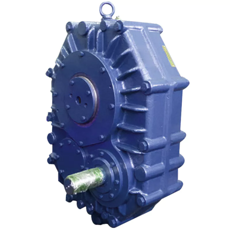
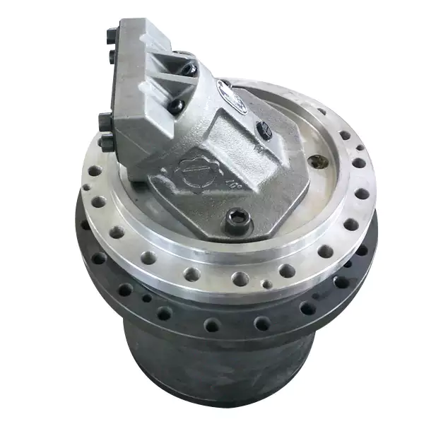
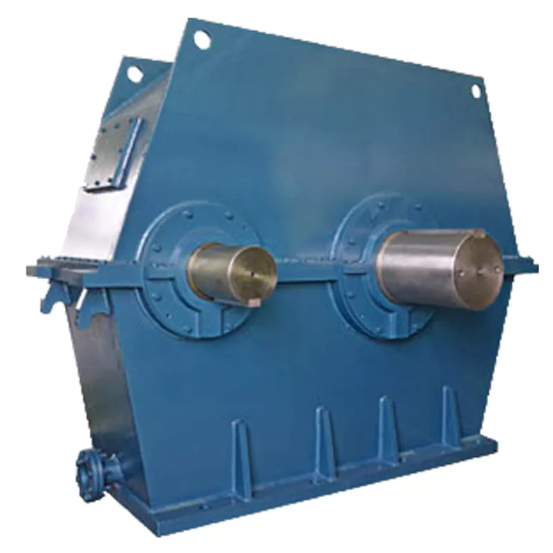
318 Series inline Planetary Gearbox Gear Reducer 318L1 318L2 318L3 318L48 318R4 replacement of bonfiglioli
Product Description
The 300L series and 300R series planetary gearboxes can be interchangeable with the following models of Trasmital Bonfiglioli
| 300L 1 | 300L 2 | 300L 3 | 300L 4 | 300R2 | 300R3 | 300R4 |
| 301L 1 | 301L 2 | 301L 3 | 301L 4 | 301R2 | 301R3 | 301R4 |
| 303L 1 | 303L 2 | 303L 3 | 303L 4 | 303R2 | 303R3 | 303R4 |
| 305L 1 | 305L 2 | 305L 3 | 305L 4 | 305R2 | 305R3 | 305R4 |
| 306L 1 | 306L 2 | 306L 3 | 306L 4 | 306R2 | 306R3 | 306R4 |
| 307L 1 | 307L 2 | 307L 3 | 307L 4 | 307R2 | 307R3 | 307R4 |
| 309L 1 | 309L 2 | 309L 3 | 309L 4 | 309R2 | 309R3 | 309R4 |
| 310L 1 | 310L 2 | 310L 3 | 310L 4 | 310R2 | 310R3 | 310R4 |
| 311L 1 | 311L 2 | 311L 3 | 311L 4 | 311R2 | 311R3 | 311R4 |
| 313L 1 | 313L 2 | 313L 3 | 313L 4 | 313R2 | 313R3 | 313R4 |
| 315L 1 | 315L 2 | 315L 3 | 315L 4 | 315R3 | 315R4 | |
| 316L 1 | 316L 2 | 316L 3 | 316L 4 | 316R3 | 316R4 | |
| 317L 1 | 317L 2 | 317L 3 | 317L 4 | 317R3 | 317R4 | |
| 318L 1 | 318L 2 | 318L 3 | 318L 4 | 318R4 | ||
| 319L 1 | 319L 2 | 319L 3 | 319L 4 | 319R4 | ||
| 321L 1 | 321L 2 | 321L 3 | 321L 4 | 321R4 |
-
Torque range
1,000 … 1,100,000 Nm (8,850 … 9,735,820 in-lb) -
Gear ratios
3.4 … 5,000 -
Transmissible Mechanical Power
up to 1,050 kW -
Brake options
Hydraulic brake
Hydraulically released parking brake on request
Electric brake
DC and AC type -
Output
Foot and flange mounted
Output shaft: CHINAMFG with key, splined, splined hollow, hollow with shrink disc -
Input
Flanged axial piston hydraulic motors
Hydraulic orbit motors
IEC and Nema motor adapters
Solid input shaft -
Applicable motors
Piston hydraulic motors
Hydraulic orbit motors
Electric motors IEC
Key Features
1. Torque range: 1000-450.000 Nm
2. Transmissible mechanical power: up to 540 kW
3. Gear ratios: 3.4-9.000
4. Gear unit versions: in line
5. Output configurations:
1) Foot and flange mounted
2) Output shaft: CHINAMFG with key, splined, splined hollow
3) Hollow with shrink disc
6. Input configurations:
1) Flanged axial piston hydraulic motors
2) Hydraulic orbit motors
3) IEC and Nema motor adaptors
4) CHINAMFG input shaft
7. Hydraulic brake: hydraulically released parking brake
8. Electric brake: DC and AC type
Application
Our factory
Related Products
For more reducers and mechanical accessories, please click here to view
| Application: | Motor, Electric Cars, Motorcycle, Machinery, Marine, Toy, Agricultural Machinery, Car |
|---|---|
| Function: | Distribution Power, Speed Changing, Speed Reduction |
| Layout: | Wrom |
| Hardness: | Hardened Tooth Surface |
| Installation: | Planetary |
| Step: | Planetary |

Are there any disadvantages or limitations to using gear reducer systems?
While gear reducer systems offer numerous advantages, they also come with certain disadvantages and limitations that should be considered during the selection and implementation process:
1. Size and Weight: Gear reducers can be bulky and heavy, especially for applications requiring high gear ratios. This can impact the overall size and weight of the machinery or equipment, which may be a concern in space-constrained environments.
2. Efficiency Loss: Despite their high efficiency, gear reducers can experience energy losses due to friction between gear teeth and other components. This can lead to a reduction in overall system efficiency, particularly in cases where multiple gear stages are used.
3. Cost: The design, manufacturing, and assembly of gear reducers can involve complex processes and precision machining, which can contribute to higher initial costs compared to other power transmission solutions.
4. Maintenance: Gear reducer systems require regular maintenance, including lubrication, inspection, and potential gear replacement over time. Maintenance activities can lead to downtime and associated costs in industrial settings.
5. Noise and Vibration: Gear reducers can generate noise and vibrations, especially at high speeds or when operating under heavy loads. Additional measures may be needed to mitigate noise and vibration issues.
6. Limited Gear Ratios: While gear reducers offer a wide range of gear ratios, there may be limitations in achieving extremely high or low ratios in certain designs.
7. Temperature Sensitivity: Extreme temperatures can affect the performance of gear reducer systems, particularly if inadequate lubrication or cooling is provided.
8. Shock Loads: While gear reducers are designed to handle shock loads to some extent, severe shock loads or abrupt changes in torque can still lead to potential damage or premature wear.
Despite these limitations, gear reducer systems remain widely used and versatile components in various industries, and their disadvantages can often be mitigated through proper design, selection, and maintenance practices.

What factors should be considered when selecting the right gear reducer?
Choosing the appropriate gear reducer involves considering several crucial factors to ensure optimal performance and efficiency for your specific application:
- 1. Torque and Power Requirements: Determine the amount of torque and power your machinery needs for its operation.
- 2. Speed Ratio: Calculate the required speed reduction or increase to match the input and output speeds.
- 3. Gear Type: Select the appropriate gear type (helical, bevel, worm, planetary, etc.) based on your application’s torque, precision, and efficiency requirements.
- 4. Mounting Options: Consider the available space and the mounting configuration that suits your machinery.
- 5. Environmental Conditions: Evaluate factors such as temperature, humidity, dust, and corrosive elements that may impact the gear reducer’s performance.
- 6. Efficiency: Assess the gear reducer’s efficiency to minimize power losses and improve overall system performance.
- 7. Backlash: Consider the acceptable level of backlash or play between gear teeth, which can affect precision.
- 8. Maintenance Requirements: Determine the maintenance intervals and procedures necessary for reliable operation.
- 9. Noise and Vibration: Evaluate noise and vibration levels to ensure they meet your machinery’s requirements.
- 10. Cost: Compare the initial cost and long-term value of different gear reducer options.
By carefully assessing these factors and consulting with gear reducer manufacturers, engineers and industry professionals can make informed decisions to select the right gear reducer for their specific application, optimizing performance, longevity, and cost-effectiveness.

Function of Gear Reducers in Mechanical Systems
A gear reducer, also known as a gear reduction unit or gearbox, is a mechanical device designed to reduce the speed of an input shaft while increasing its torque output. It accomplishes this through the use of a set of interlocking gears with different sizes.
The primary function of a gear reducer in mechanical systems is to:
- Speed Reduction: The gear reducer takes the high-speed rotation of the input shaft and transmits it to the output shaft through a set of gears. The gears are configured in such a way that the output gear has a larger diameter than the input gear. As a result, the output shaft rotates at a lower speed than the input shaft, but with increased torque.
- Torque Increase: Due to the size difference between the input and output gears, the torque applied to the output shaft is greater than that of the input shaft. This torque multiplication allows the system to handle heavier loads and perform tasks requiring higher force.
Gear reducers are widely used in various industries and applications where it’s necessary to adapt the speed and torque characteristics of a power source to meet the requirements of the driven equipment. They can be found in machinery such as conveyor systems, industrial machinery, vehicles, and more.


editor by CX 2023-09-13