Product Description
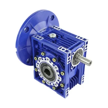
NMRV REDUCTION WORM GEARBOX
The NMRV 040 worm gear motor is characterized by a wide range of gear ratios (5 – 80), a compact aluminum alloy housing, and ease of installation and maintenance. The unit is equipped with an engine power of 0.09 – 0.55 kW. Output shaft rotation frequency: 900 – 2800 rpm.
The NMRV 040 motor gearbox has similar mounting dimensions with the Siti MU40, STM UMI 40, Varvel SRT 40 drives and can be used to replace them.
Parts materials:
Case – aluminum, flanges – aluminum, worm – steel, worm wheel CHINAMFG – bronze.
Type of lubricant: synthetic ISO VG 320.
Weight: 2.3 kg.
Type designation scheme
NMRV – 040 – 80 – 17.5 – 0.12 – B3
- NMRV – worm gear motor
- 040 – size (center distance, mm)
- 80 – gear ratio
- 17.5 – output shaft rotation speed, rpm
- 0,12 – electric motor power, kW
- B3 – mounting position
NMRV 040 gearbox performance
| I |
n 1 = 2800 rpm | n 1 = 1400 rpm | n 1 = 900, rpm | |||||||||
| n 2 , rpm |
T 2M , N * m |
P kw |
RD % |
n 2 , rpm |
T 2M , N * m |
P kw |
RD % |
n 2 , rpm |
T 2M , N * m |
P kw |
RD % |
|
| 5 | 560 | 24 | 1.50 | 87 | 280 | 36 | 1.10 | 86 | 180 | 41 | 0.80 | 84 |
| 7.5 | 373 | 29 | 1.30 | 88 | 187 | 41 | 0.93 | 86 | 120 | 49 | 0.73 | 84 |
| 10 | 280 | 32 | 1.10 | 86 | 140 | 44 | 0.76 | 84 | 90 | 50 | 0.58 | 82 |
| 15 | 187 | 34 | 0.78 | 84 | 93 | 44 | 0.53 | 81 | 60 | 52 | 0.41 | 79 |
| 20 | 140 | 31 | 0.56 | 82 | 70 | 40 | 0.37 | 79 | 45 | 47 | 0.29 | 76 |
| 25 | 112 | 34 | 0.50 | 79 | 56 | 43 | 0.34 | 74 | 36 | 49 | 0.26 | 71 |
| 30 | 93 | 33 | 0.44 | 73 | 47 | 38 | 0.27 | 68 | 30 | 43 | 0.21 | 65 |
| 40 | 70 | 35 | 0.36 | 72 | 35 | 44 | 0.24 | 67 | 23 | 52 | 0.19 | 64 |
| 50 | 56 | 32 | 0.29 | 65 | 28 | 41 | 0.20 | 60 | 18 | 48 | 0.16 | 57 |
| 60 | 47 | 29 | 0.24 | 59 | 23 | 38 | 0.17 | 54 | 15 | 41 | 0.13 | 50 |
| 80 | 35 | 23 | 0.15 | 56 | 18 | 31 | 0.11 | 51 | 11 | 37 | 0.09 | 49 |
| 100 | 28 | 24 | 0.13 | 53 | 14 | 29 | 0.09 | 48 | 9 | 33 | 0.07 | 44 |
- n1 – rotational speed el. engine;
- n2 – revolutions on the output shaft;
- T 2M – torque on the output shaft;
- P is the maximum allowable engine power;
- RD – efficiency
GEARBOX FEATURE
| 1.Good quality,long life time,low noise. |
| 3.High efficiency,big torque. |
Overall and mounting dimensions NMRV 040
NMRV040 gear motor has a wide range of gear ratios.
Gear ratios: 5, 7.5, 10, 15, 20, 25, 30, 40, 50, 60, 80, 100 .
Output flange to NMRV 040 gearbox
Geared NMRV040 can be supplied with unilateral or bilateral output shaft.
The gearbox comes standard with a hollow output shaft
A torque arm is an additional option to the gearbox.
| Model | NMRV SERIES |
| Single Stage | RV25-RV150 |
| Ratio | 7.5-100 |
| Input Power | 0.06KW-15KW |
| Output Speed | 14-280rpm |
| Output Torque | 5-1800Nm |
| Core parts | worm wheel,worm shaft |
| Core parts material | worm shaft:20 Cr Mn Ti,worm wheel:Nodular cast iron interal,9-4 copper external |
| Lubrication | RV30-90:synthetic oil, RV110-150:GN460-W mineral oil |
| Bearings | C&U |
| Application: | Motor, Motorcycle, Machinery, Agricultural Machinery, Industry |
|---|---|
| Hardness: | Hardened |
| Installation: | Any Angle |
| Gear Shape: | Worm Gear |
| Step: | Single-Step |
| Type: | Worm and Wormwheel |
| Samples: |
US$ 20/Piece
1 Piece(Min.Order) | |
|---|
| Customization: |
Available
| Customized Request |
|---|

Calculating Gear Ratio in a Worm Reducer
The gear ratio in a worm reducer is determined by the number of teeth on the worm wheel (also known as the worm gear) and the number of threads on the worm shaft. The gear ratio formula for a worm reducer is:
Gear Ratio = Number of Teeth on Worm Wheel / Number of Threads on Worm Shaft
For example, if the worm wheel has 60 teeth and the worm shaft has a single thread, the gear ratio would be 60:1.
It’s important to note that worm reducers have an inherent self-locking property due to the angle of the worm threads. As a result, the gear ratio also affects the mechanical advantage and the system’s ability to resist backdriving.
When calculating the gear ratio, ensure that the worm reducer is properly designed and that the gear ratio aligns with the desired mechanical characteristics for your application. Additionally, consider factors such as efficiency, load capacity, and speed limitations when selecting a gear ratio for a worm reducer.

Worm Gearboxes in Conveyor Systems: Benefits and Considerations
Worm gearboxes play a crucial role in conveyor systems, offering several benefits and considerations for their effective integration:
- Space Efficiency: Worm gearboxes have a compact design, making them suitable for applications with limited space, such as conveyor systems.
- High Reduction Ratios: Worm gearboxes can achieve high reduction ratios in a single stage, allowing for slower conveyor speeds without sacrificing torque.
- Self-Locking: Worm gearboxes have inherent self-locking properties, preventing the conveyor from moving when the motor is not actively driving it.
- Directional Control: Worm gearboxes facilitate directional control, enabling the conveyor to move forward or reverse as needed.
- Low Noise: Worm gearboxes often produce lower noise levels compared to other gearbox types, contributing to quieter conveyor operation.
However, there are also considerations to keep in mind when using worm gearboxes in conveyor systems:
- Efficiency: Worm gearboxes may have lower mechanical efficiency compared to some other gearbox types, leading to energy losses.
- Heat Generation: Worm gearboxes can generate more heat due to sliding contact between the worm and gear, necessitating proper cooling mechanisms.
- Lubrication: Proper lubrication is critical to prevent wear and ensure efficient operation. Regular maintenance is required to monitor lubrication levels.
- Load and Speed: Worm gearboxes are well-suited for applications with high torque and low to moderate speed requirements. They may not be optimal for high-speed conveyors.
Before integrating a worm gearbox into a conveyor system, it’s important to carefully consider the specific requirements of the application, including load, speed, space constraints, and efficiency needs. Consulting with gearbox experts and manufacturers can help ensure the right choice for the conveyor’s performance and longevity.

Types of Worm Gear Configurations and Their Uses
Worm gear configurations vary based on the arrangement of the worm and the gear it engages with. Here are common types and their applications:
- Single Enveloping Worm Gear: This configuration offers high torque transmission and efficiency. It’s used in heavy-duty applications like mining equipment and industrial machinery.
- Double Enveloping Worm Gear: With increased contact area, this type provides higher load capacity and improved efficiency. It’s used in aerospace applications, robotics, and precision machinery.
- Non-Throated Worm Gear: This type has a cylindrical worm without a throat. It’s suitable for applications requiring precise motion control, such as CNC machines and robotics.
- Throated Worm Gear: Featuring a throat in the worm, this configuration offers smooth engagement and higher load capacity. It’s used in conveyors, elevators, and automotive applications.
- Non-Modular Worm Gear: In this design, the worm and gear are a matched set, resulting in better meshing and efficiency. It’s utilized in various industries where customization is essential.
- Modular Worm Gear: This type allows interchangeability of worm and gear components, providing flexibility in design and maintenance. It’s commonly used in conveyors, mixers, and material handling systems.
Selecting the appropriate worm gear configuration depends on factors such as load capacity, efficiency, precision, and application requirements. Consulting gearbox experts can help determine the best configuration for your specific needs.


editor by CX 2023-09-13