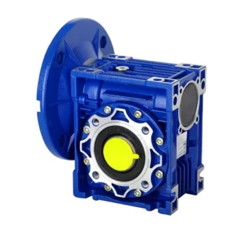
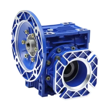
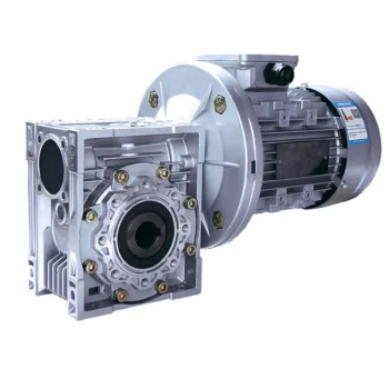
Product Description
Recommended by seller
Technical features
The high degree of modularity is a design feature of SKM.SKB series helical-hypoid gear unit. It can be connected respectively with motors such as normal motor, brake motor, explosion-proof motor, frequency conversion motor, servo motor, IEC motor and so on. This kind of product is widely used in drive fields such as textile, footstuff, ceramice packing, logistic, plastics and so on
Product Parameters
|
Applicable Industries |
Garment Shops, Manufacturing Plant, Machinery Repair Shops, Food & Beverage Factory |
|
Gearing Arrangement |
Hypoid |
|
Output Torque |
100~500NM |
|
Input Speed |
1400rpm |
|
Output Speed |
5~187 |
|
Place of Origin |
China |
|
Brand Name |
HUAKE |
|
Product name |
Hypoid gear reducer |
|
Color |
Blue |
|
Ratio |
5-400 |
|
Certificate |
ISO9001 CCC CE |
Products characteristics
SKM SKB Series helical gear units has more than 4 types, power 0.12-4kw, ratio 7.73-302.5, torque max 100-500NM, Modulaw and multistructure can meet the demands of various conditions.
(1) Ground-hardened helical gears.
(2) Modularity, can be combined in many forms
(3) Made of high-quality aluminum alloy, light in weight and nonrusting
(4)Large in output torque, high efficiencym energy saving and environmental protection
(5) The mounting dimension of SKM series are compatible with SMRV series worm gear unit
(A part of SMRV050 dimensions are different from SKM28)
(6) The mounting dimension of SKB series are compatible with W series worm gear unit.
Features&Specification
SKM28B~SKM58B:2-Stage hypoid helical gear units. Speed ratio range7.48~60.5 SKM28C~SKM58C:3-Stage hypoid helical gear units. Speed ratio range:4918~302.5 One of the features of the hypoid gear speed reducer is that the shafts intersect at 2 mutually parallel planes,providing greater torque in the same construction space than an ordinary helical gear reducer. And its strength is much higher than that of worm gear reducer. 1.Omnidirectional mounting 2.Housing made of high-quality aluminum alloydie-casting,light weight good rust resistance 3.Low back clearance 4.Smooth transmission and low noise 5.Customized products available
For more models, please contact us!
F helical gear reducer
Parallel output, compact structure, large transmission torque, stable operation, low noise and long life.
Installation method: base installation, flange installation, torque arm installation.
Reduction ratio: basic type 2 level 4.3-25.3, 3 level 28.2-273, combined to 18509.
The rotation direction of the input and output of the basic two-stage is the same, and the three-stage is opposite; please consult when combining.
Output mode: hollow shaft output or CHINAMFG shaft output.
Average efficiency: Level 2 96%, Level 3 94%, F/CR average efficiency 85%.
K helical bevel gear reducer
Vertical output, compact structure, hard tooth surface transmission torque, high-precision gears ensure stable work, low noise
and long life.
Installation method: base installation, flange installation, torque arm installation, small flange installation.
Input mode: motor direct connection, motor belt connection or input shaft, connection flange input.
Output mode: hollow shaft output or CHINAMFG shaft output, the average efficiency is 94%.
Reduction ratio: basic type 8.1-191, combined to 13459.
R helical gear reducer
Small bias output, compact structure, maximum use of cabinet space, the second and third levels are in the same cabinet. Using an integral cast box, the box structure has good rigidity, which is easy to improve the strength of the shaft and the life of the
bearing.
Installation method: pedestal installation, flanges with large and small flanges are easy to choose.
Solid shaft output, the average efficiency is 96% in the second stage, 94% in the third stage, and 85% in CR/CR. The CRM series specially designed for mixing can carry large axial and radial forces.
Company Profile
Certifications
Packaging & Shipping
FAQ
| Application: | Motor, Electric Cars, Motorcycle, Machinery, Marine, Toy, Agricultural Machinery, Car, Transmission Parts |
|---|---|
| Function: | Distribution Power, Clutch, Change Drive Torque, Change Drive Direction, Speed Changing, Speed Reduction, Speed Increase |
| Layout: | Cycloidal |
| Hardness: | Hardened Tooth Surface |
| Installation: | Torque Arm Type |
| Step: | Single-Step |
| Samples: |
US$ 80/Piece
1 Piece(Min.Order) | |
|---|

How to Install and Align a Worm Reducer Properly
Proper installation and alignment of a worm reducer are crucial for ensuring optimal performance and longevity. Follow these steps to install and align a worm reducer:
- Preparation: Gather all the necessary tools, equipment, and safety gear before starting the installation process.
- Positioning: Place the worm reducer in the desired location, ensuring that it is securely mounted to a stable surface. Use appropriate fasteners and mounting brackets as needed.
- Shaft Alignment: Check the alignment of the input and output shafts. Use precision measurement tools to ensure that the shafts are parallel and in line with each other.
- Base Plate Alignment: Align the base plate of the reducer with the foundation or mounting surface. Ensure that the base plate is level and properly aligned before securing it in place.
- Bolt Tightening: Gradually and evenly tighten the mounting bolts to the manufacturer’s specifications. This helps ensure proper contact between the reducer and the mounting surface.
- Check for Clearance: Verify that there is enough clearance for any rotating components or parts that may move during operation. Avoid any interference that could cause damage or performance issues.
- Lubrication: Apply the recommended lubricant to the worm reducer according to the manufacturer’s guidelines. Proper lubrication is essential for smooth operation and reducing friction.
- Alignment Testing: After installation, run the worm reducer briefly without a load to check for any unusual noises, vibrations, or misalignment issues.
- Load Testing: Gradually introduce the intended load to the worm reducer and monitor its performance. Ensure that the reducer operates smoothly and efficiently under the load conditions.
It’s important to refer to the manufacturer’s installation guidelines and specifications for your specific worm reducer model. Proper installation and alignment will contribute to the gearbox’s reliability, efficiency, and overall functionality.

How to Calculate the Input and Output Speeds of a Worm Gearbox?
Calculating the input and output speeds of a worm gearbox involves understanding the gear ratio and the principles of gear reduction. Here’s how you can calculate these speeds:
- Input Speed: The input speed (N1) is the speed of the driving gear, which is the worm gear in this case. It is usually provided by the manufacturer or can be measured directly.
- Output Speed: The output speed (N2) is the speed of the driven gear, which is the worm wheel. To calculate the output speed, use the formula:
N2 = N1 / (Z1 * i)
Where:
N2 = Output speed (rpm)
N1 = Input speed (rpm)
Z1 = Number of teeth on the worm gear
i = Gear ratio (ratio of the number of teeth on the worm gear to the number of threads on the worm)
It’s important to note that worm gearboxes are designed for gear reduction, which means that the output speed is lower than the input speed. Additionally, the efficiency of the gearbox, friction, and other factors can affect the actual output speed. Calculating the input and output speeds is crucial for understanding the performance and capabilities of the worm gearbox in a specific application.

Preventing Backlash in a Worm Gearbox
Backlash in a worm gearbox can lead to reduced accuracy, positioning errors, and decreased overall efficiency. Here are steps to prevent or minimize backlash:
- High-Quality Components: Use high-quality worm gears and worm wheels with tight manufacturing tolerances. Precision components will help reduce backlash.
- Proper Meshing: Ensure the worm gear and worm wheel are properly aligned and meshed. Improper meshing can lead to increased backlash.
- Preload: Applying a small amount of preload to the worm gear can help reduce backlash. However, excessive preload can increase friction and wear.
- Anti-Backlash Mechanisms: Consider using anti-backlash mechanisms, such as spring-loaded systems or adjustable shims, to compensate for any inherent backlash.
- Lubrication: Proper lubrication can reduce friction and play a role in minimizing backlash. Use a lubricant that provides good film strength and reduces wear.
- Maintenance: Regularly inspect and maintain the gearbox to identify and address any changes in backlash over time.
It’s important to strike a balance between reducing backlash and maintaining smooth operation. Consulting with gearbox experts and following manufacturer guidelines will help you optimize your worm gearbox’s performance while minimizing backlash.


editor by CX 2023-09-13