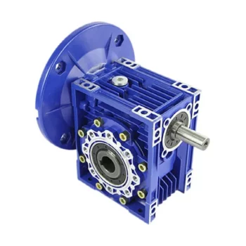
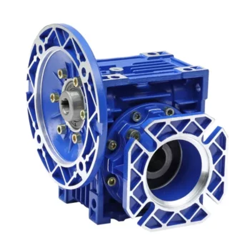
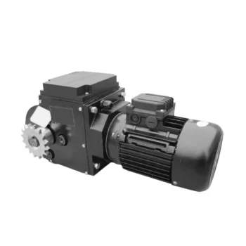
Product Description
Features
1.Wide transmission rate, strong output torque
2.Compact mechanical structure, light weight, small volume&Good heat-dissipating
3.Smooth operation with lower noise or vibration
4.Easy mounting, free linking, high efficiency
5. PERFECT SUBSTITUDE FOR MOTOVARIO AND CHINAMFG PRODUCTS
Applications
Wide range of application,including light industry of food &beverage, Cement,
package,construction material,chemicals and etc.
Technical data:
| Model | RV 130 150 |
| Single unit versions | NMRV – fitted for motor flanged coupling, NRV – with input shaft, NMRV-E motor flanged coupling with worm extension shaft, NRV-E with double extension worm shaft, |
| Power | 0.06—-15KW |
| Single unit reduction ratio | 1:5 7.5 80 100 |
| Output torque | 2.6—1195N.M |
| Worm shaft material | 20CrMnTi with carburizing and quenching.The hardness of surface is 56-62HRC with carbonized layer 0.5-0.8mm |
| Worm wheel material | worm mandrel is HT250,and worm ring gear,ZQSn10-1,hardness is 60HRC |
After-sale service:
One year warranty,subject to proper operation and installation;free technical support all the time.
|
Shipping Cost:
Estimated freight per unit. |
To be negotiated |
|---|
| Application: | Motor |
|---|---|
| Hardness: | Hardened |
| Type: | Worm and Wormwheel |
| Samples: |
US$ 40/Piece
1 Piece(Min.Order) | Order Sample |
|---|
| Customization: |
Available
| Customized Request |
|---|

Calculating Gear Ratio in a Worm Reducer
The gear ratio in a worm reducer is determined by the number of teeth on the worm wheel (also known as the worm gear) and the number of threads on the worm shaft. The gear ratio formula for a worm reducer is:
Gear Ratio = Number of Teeth on Worm Wheel / Number of Threads on Worm Shaft
For example, if the worm wheel has 60 teeth and the worm shaft has a single thread, the gear ratio would be 60:1.
It’s important to note that worm reducers have an inherent self-locking property due to the angle of the worm threads. As a result, the gear ratio also affects the mechanical advantage and the system’s ability to resist backdriving.
When calculating the gear ratio, ensure that the worm reducer is properly designed and that the gear ratio aligns with the desired mechanical characteristics for your application. Additionally, consider factors such as efficiency, load capacity, and speed limitations when selecting a gear ratio for a worm reducer.

How to Calculate the Input and Output Speeds of a Worm Gearbox?
Calculating the input and output speeds of a worm gearbox involves understanding the gear ratio and the principles of gear reduction. Here’s how you can calculate these speeds:
- Input Speed: The input speed (N1) is the speed of the driving gear, which is the worm gear in this case. It is usually provided by the manufacturer or can be measured directly.
- Output Speed: The output speed (N2) is the speed of the driven gear, which is the worm wheel. To calculate the output speed, use the formula:
N2 = N1 / (Z1 * i)
Where:
N2 = Output speed (rpm)
N1 = Input speed (rpm)
Z1 = Number of teeth on the worm gear
i = Gear ratio (ratio of the number of teeth on the worm gear to the number of threads on the worm)
It’s important to note that worm gearboxes are designed for gear reduction, which means that the output speed is lower than the input speed. Additionally, the efficiency of the gearbox, friction, and other factors can affect the actual output speed. Calculating the input and output speeds is crucial for understanding the performance and capabilities of the worm gearbox in a specific application.

Lubrication Requirements for a Worm Gearbox
Lubrication is crucial for maintaining the performance and longevity of a worm gearbox. Here are the key considerations for lubricating a worm gearbox:
- Type of Lubricant: Use a high-quality, high-viscosity lubricant specifically designed for worm gearboxes. Worm gearboxes require lubricants with additives that provide proper lubrication and prevent wear.
- Lubrication Interval: Follow the manufacturer’s recommendations for lubrication intervals. Regularly check the gearbox’s temperature and oil condition to determine the optimal frequency of lubrication.
- Oil Level: Maintain the proper oil level to ensure effective lubrication. Too little oil can lead to insufficient lubrication, while too much oil can cause overheating and foaming.
- Lubrication Points: Identify all the lubrication points on the gearbox, including the worm and wheel gear surfaces. Apply the lubricant evenly to ensure complete coverage.
- Temperature: Consider the operating temperature of the gearbox. Some lubricants have temperature limits, and extreme temperatures can affect lubricant viscosity and performance.
- Cleanliness: Keep the gearbox and the surrounding area clean to prevent contaminants from entering the lubricant. Use proper filtration and seals to maintain a clean environment.
- Monitoring: Regularly monitor the gearbox’s temperature, noise level, and vibration to detect any signs of inadequate lubrication or other issues.
Proper lubrication will reduce friction, wear, and heat generation, ensuring smooth and efficient operation of the worm gearbox. Always refer to the manufacturer’s guidelines for lubrication specifications and intervals.


editor by CX 2023-09-13