Product Description
Product Parameters
1.German spindle design which is the widely used in the industry with proven performance
2.Low-alloy machined spindles, friction welded seamlessly, and overall heat treating process
3.Axle stubs and brake hubs are all CZPT forging, ensure they are more powerful and better steady
4.Special clone-shape design on the axle-shoulders, lessening stress concentration and enhancing anti-fatigue performance
5.Unique design on axle stubs (with a precise declination angel at both ends) to minimize tire wear
6.National and industry standard compliant set components
7.National Automobile Monitor and Inspection Center certified axle shaft that undergoes over 1.2 million times of Fatigue testing and built to meet or exceed national industry standards.
|
Axle Type
|
Max Capacity (T) |
L2 Track (mm) |
Brake ( mm )
|
Bearing |
Spring Seat Installation
|
Axle
|
L4Centre Distanceof Brake Chamber ( mm)
|
|
JS12FA1347D |
12 |
1840 |
φ420x 180 |
33118 33213 |
≥980 |
150 |
423 |
|
JS13FA1348D |
13 |
1840 |
φ 420x 200 |
33118 33213
|
≥900 |
150 |
360 |
|
JS14FA1348D |
14 |
1840 |
φ 420x 200 |
32219 33215 |
≥900 |
150 |
356 |
|
JS16FA1348D |
16 |
1850 |
φ 420x 200 |
322222 32314 |
≥900 |
150 |
360 |
|
JS18FA1348D |
18 |
1850 |
Φ420x 200 |
322222 32314 |
≥900 |
150 |
380 |
|
Wheel Fixing
|
Total Length ( mm )
|
Recommended Wheel
|
Weigth(Kg)
|
||
|
Stud
|
PCD(mm) |
H(mm) |
|||
|
10-M22x 1.5ISO |
335 |
280.8 |
~ 2144 |
7.5v-20 |
360 |
|
10-M22x 1.5ISO |
335 |
280.8 |
~ 2144 |
7.5v-20 |
382 |
|
10-M22x 1.5ISO |
335 |
280.8 |
~ 2198 |
8.0v-20 |
406 |
|
10-M22x 1.5ISO |
335 |
280.8 |
~ 2265 |
8.5v-20 |
440 |
|
10-M22x 1.5ISO |
335 |
280.8 |
~ 2265 |
8.5v-20 |
443 |
Detailed Photos
Application
Company Profile
ZheJiang CZPT Axle Manufacturing Co., Ltd., founded in 2000, is a professional manufacturer of trailer axle assemblies, semi-trailer suspension systems and correlative fittings in China. We are located in Quanpu Industry Zone which is the largest production base of trailers in China, in Xihu (West Lake) Dis., the famous scenic spot. We are 1 of specialized enterprises in the scientific research, design, production and sale, with more than 300 skilled employees and professional designers for different areas. We adopt the domestic and international technical standards in production, accurately grasp the information of the market demand and make quick and optimal designs. In this way, our axle, suspension and other fittings have the world-class technical quality through reasonable and advanced manufacture technologies. Our advanced processing technology, first-class production line and precision CNC machining equipment from home and abroad ensure the good quality of our semi-trailer axle assemblies, suspension systems and other correlative fittings. At the same time, our annual capacity for the export of American and German semi-trailer axle assemblies has achieved 60, 000 pieces and of suspension assemblies has achieved 50, 000 sets. We obtained the ISO9001: 2000 International Quality Management System Certification in 2003 and TS16949 Certification in 2007. “First-class product quality, the meticulous and thoughtful service, and CZPT cooperation” is the philosophy that we always cherish. We not only meet the domestic market demand, but also export our products to Southeast Asia, the Middle East, Latin America and other countries, enjoying a good reputation. We always regard quality as life, and client as God. We will create a brilliant tomorrow with your sincere cooperation and support.
Certifications
Packaging & Shipping
FAQ
1. What’s your advantage?
— We are manufacturer, we own professinal technology & quality control team; excellent team for foreign trade plus a rich expertise in trading.
2.Where your export to?
— Our export to America, Netherlands, Germany, Italy, Poland, Hungary, Russia, and other European, Asia and Africa countries.
3. Can you send me samples for testing?
— Certainly! We’d like to provide the samples free of charge, but for the freight, pls kindly bear it.
4.Can you supply OEM ?
— Sure, we always supply customized seveices according to customers’ drawing or samples.
5. How long do you finish a new product?
— Usually 20~35days once all information confirmed.
Remark:
Our payment terms
— 30% by T/T in advance, 70% by T/T before shipment
/* January 22, 2571 19:08:37 */!function(){function s(e,r){var a,o={};try{e&&e.split(“,”).forEach(function(e,t){e&&(a=e.match(/(.*?):(.*)$/))&&1
| After-sales Service: | 24 Hours Online |
|---|---|
| Condition: | New |
| Axle Number: | 2 |
| Application: | Trailer |
| Certification: | CE, ISO |
| Material: | Iron |
| Samples: |
US$ 490/Piece
1 Piece(Min.Order) | |
|---|
| Customization: |
Available
| Customized Request |
|---|
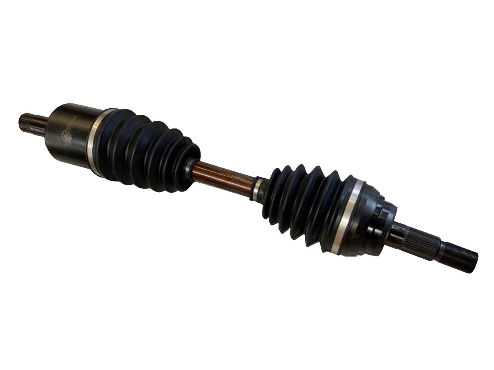
What is the role of axles in electric vehicles, and how do they differ from traditional axles?
Electric vehicles (EVs) have unique requirements when it comes to their drivetrain systems, including the axles. The role of axles in EVs is similar to traditional vehicles, but there are some key differences. Here’s a detailed explanation of the role of axles in electric vehicles and how they differ from traditional axles:
Role of Axles in Electric Vehicles:
The primary role of axles in electric vehicles is to transmit torque from the electric motor(s) to the wheels, enabling vehicle propulsion. The axles connect the motor(s) to the wheels and provide support for the weight of the vehicle. Axles are responsible for transferring the rotational force generated by the electric motor(s) to the wheels, allowing the vehicle to move forward or backward.
In electric vehicles, the axles are an integral part of the drivetrain system, which typically includes an electric motor(s), power electronics, and a battery pack. The axles play a crucial role in ensuring efficient power transfer and delivering the desired performance and handling characteristics of the vehicle.
Differences from Traditional Axles:
While the fundamental role of axles in electric vehicles is the same as in traditional vehicles, there are some notable differences due to the unique characteristics of electric propulsion systems:
1. Integration with Electric Motors: In electric vehicles, the axles are often integrated with the electric motors. This means that the motor(s) and axle assembly are combined into a single unit, commonly referred to as an “electric axle” or “e-axle.” This integration helps reduce the overall size and weight of the drivetrain system and simplifies installation in the vehicle.
2. High Torque Requirements: Electric motors generate high amounts of torque from the moment they start, providing instant acceleration. As a result, axles in electric vehicles need to handle higher torque loads compared to traditional axles. They are designed to withstand the torque output of the electric motor(s) and efficiently transmit it to the wheels.
3. Regenerative Braking: Electric vehicles often utilize regenerative braking, which converts the vehicle’s kinetic energy into electrical energy and stores it in the battery. The axles in electric vehicles may incorporate systems or components that enable regenerative braking, such as sensors, controllers, and electric brake actuators.
4. Space Optimization: Electric vehicles often have different packaging requirements compared to traditional internal combustion engine vehicles. The axles in electric vehicles are designed to accommodate the space constraints and specific layout of the vehicle, considering the placement of the battery pack, electric motor(s), and other components.
5. Weight Considerations: Electric vehicles strive to optimize weight distribution to enhance efficiency and handling. Axles in electric vehicles may be designed with lightweight materials or innovative construction techniques to minimize weight while maintaining structural integrity and durability.
It’s important to note that the specific design and characteristics of axles in electric vehicles can vary depending on the vehicle manufacturer, drivetrain configuration (e.g., front-wheel drive, rear-wheel drive, all-wheel drive), and other factors. Automotive manufacturers and suppliers continually innovate and develop new axle technologies to meet the evolving demands of electric vehicle propulsion systems.
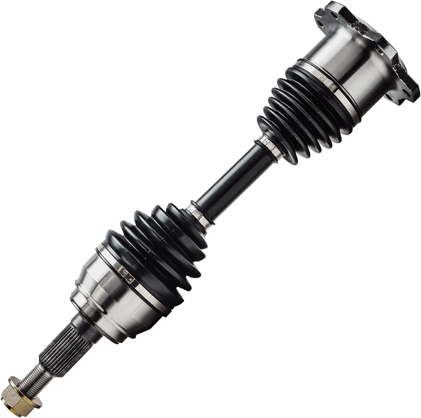
What are the symptoms of a failing CV joint, and how does it relate to the axle?
A CV (constant velocity) joint is an essential component of the axle assembly in many vehicles. When a CV joint starts to fail, it can exhibit several symptoms that indicate potential problems. Here’s a detailed explanation of the symptoms of a failing CV joint and its relationship to the axle:
Symptoms of a Failing CV Joint:
1. Clicking or popping sounds: One of the most common signs of a failing CV joint is a clicking or popping sound when making turns. This noise usually occurs during tight turns and may indicate worn-out or damaged CV joint bearings.
2. Grease leakage: A failing CV joint may leak grease, which can be seen as dark-colored grease splattered around the CV joint or on the inside of the wheel. Grease leakage is typically caused by a cracked or damaged CV joint boot, which allows the lubricating grease to escape and contaminants to enter.
3. Excessive vibration: A worn-out CV joint can cause vibrations, especially during acceleration. The vibrations may be felt in the steering wheel, floorboards, or even the entire vehicle. These vibrations can become more noticeable as the CV joint deteriorates further.
4. Difficulty in turning: As the CV joint wears out, it may become difficult to turn the vehicle, especially at low speeds or when making sharp turns. This symptom is often accompanied by a clicking or popping sound.
5. Uneven tire wear: A failing CV joint can lead to uneven tire wear. If the CV joint is damaged or worn, it can cause the axle to wobble or vibrate, resulting in uneven tire tread wear. This can be observed by visually inspecting the tires and noticing uneven patterns of wear.
Relationship to the Axle:
The CV joint is an integral part of the axle assembly. It connects the transmission to the wheels and allows smooth power delivery to the wheels while accommodating the up-and-down motion of the suspension. The axle shaft is responsible for transmitting torque from the transmission to the CV joints and ultimately to the wheels.
Axles contain one or more CV joints, depending on the vehicle’s drivetrain configuration. In front-wheel drive vehicles, each front axle typically has two CV joints, one inner and one outer. Rear-wheel drive and all-wheel drive vehicles may have CV joints on both the front and rear axles.
The CV joint consists of a joint housing, bearings, and internal ball bearings or rollers. It is protected by a rubber or thermoplastic CV joint boot, which seals in the grease and protects the joint from contaminants. When the CV joint fails, it can affect the axle’s ability to transmit power smoothly and result in the symptoms mentioned above.
Regular inspection and maintenance of the CV joint and axle assembly are crucial to identify and address any issues promptly. If any of the symptoms mentioned earlier are observed, it is recommended to have the vehicle inspected by a qualified mechanic to determine the exact cause and perform necessary repairs or replacements.
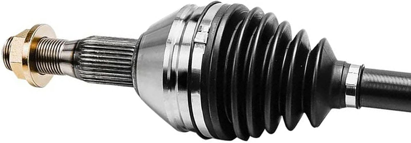
What is the primary function of an axle in a vehicle or machinery?
An axle plays a vital role in both vehicles and machinery, providing essential functions for their operation. The primary function of an axle is to transmit rotational motion and torque from an engine or power source to the wheels or other rotating components. Here are the key functions of an axle:
- Power Transmission:
- Support and Load Bearing:
- Wheel and Component Alignment:
- Suspension and Absorption of Shocks:
- Steering Control:
- Braking:
An axle serves as a mechanical link between the engine or power source and the wheels or driven components. It transfers rotational motion and torque generated by the engine to the wheels, enabling the vehicle or machinery to move. As the engine rotates the axle, the rotational force is transmitted to the wheels, propelling the vehicle forward or driving the machinery’s various components.
An axle provides structural support and load-bearing capability, especially in vehicles. It bears the weight of the vehicle or machinery and distributes it evenly across the wheels or supporting components. This load-bearing function ensures stability, balance, and proper weight distribution, contributing to safe and efficient operation.
The axle helps maintain proper alignment of the wheels or rotating components. It ensures that the wheels are parallel to each other and perpendicular to the ground, promoting stability and optimal tire contact with the road surface. In machinery, the axle aligns and supports the rotating components, ensuring their correct positioning and enabling smooth and efficient operation.
In vehicles, particularly those with independent suspension systems, the axle plays a role in the suspension system’s operation. It may incorporate features such as differential gears, CV joints, or other mechanisms that allow the wheels to move independently while maintaining power transfer. The axle also contributes to absorbing shocks and vibrations caused by road irregularities, enhancing ride comfort and vehicle handling.
In some vehicles, such as trucks or buses, the front axle also serves as a steering axle. It connects to the steering mechanism, allowing the driver to control the direction of the vehicle. By turning the axle, the driver can steer the wheels, enabling precise maneuverability and navigation.
An axle often integrates braking components, such as brake discs, calipers, or drums. These braking mechanisms are actuated when the driver applies the brakes, creating friction against the rotating axle or wheels and causing deceleration or stopping of the vehicle. The axle’s design can affect braking performance, ensuring effective and reliable stopping power.
Overall, the primary function of an axle in both vehicles and machinery is to transmit rotational motion, torque, and power from the engine or power source to the wheels or rotating components. Additionally, it provides support, load-bearing capability, alignment, suspension, steering control, and braking functions, depending on the specific application and design requirements.


editor by CX 2024-04-22
China Professional AC Motor Worm Gearbox for Textile Industries cycloidal gearbox
Product Description
Features
1.Wide transmission rate, strong output torque
2.Compact mechanical structure, light weight, small volume&Good heat-dissipating
3.Smooth operation with lower noise or vibration
4.Easy mounting, free linking, high efficiency
5. PERFECT SUBSTITUDE FOR MOTOVARIO AND CHINAMFG PRODUCTS
Applications
Wide range of application,including light industry of food &beverage, Cement,
package,construction material,chemicals and etc.
Technical data:
| Model | RV 130 150 |
| Single unit versions | NMRV – fitted for motor flanged coupling, NRV – with input shaft, NMRV-E motor flanged coupling with worm extension shaft, NRV-E with double extension worm shaft, |
| Power | 0.06—-15KW |
| Single unit reduction ratio | 1:5 7.5 80 100 |
| Output torque | 2.6—1195N.M |
| Worm shaft material | 20CrMnTi with carburizing and quenching.The hardness of surface is 56-62HRC with carbonized layer 0.5-0.8mm |
| Worm wheel material | worm mandrel is HT250,and worm ring gear,ZQSn10-1,hardness is 60HRC |
After-sale service:
One year warranty,subject to proper operation and installation;free technical support all the time.
|
Shipping Cost:
Estimated freight per unit. |
To be negotiated |
|---|
| Application: | Motor |
|---|---|
| Hardness: | Hardened |
| Type: | Worm and Wormwheel |
| Samples: |
US$ 40/Piece
1 Piece(Min.Order) | Order Sample |
|---|
| Customization: |
Available
| Customized Request |
|---|
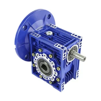
Calculating Gear Ratio in a Worm Reducer
The gear ratio in a worm reducer is determined by the number of teeth on the worm wheel (also known as the worm gear) and the number of threads on the worm shaft. The gear ratio formula for a worm reducer is:
Gear Ratio = Number of Teeth on Worm Wheel / Number of Threads on Worm Shaft
For example, if the worm wheel has 60 teeth and the worm shaft has a single thread, the gear ratio would be 60:1.
It’s important to note that worm reducers have an inherent self-locking property due to the angle of the worm threads. As a result, the gear ratio also affects the mechanical advantage and the system’s ability to resist backdriving.
When calculating the gear ratio, ensure that the worm reducer is properly designed and that the gear ratio aligns with the desired mechanical characteristics for your application. Additionally, consider factors such as efficiency, load capacity, and speed limitations when selecting a gear ratio for a worm reducer.
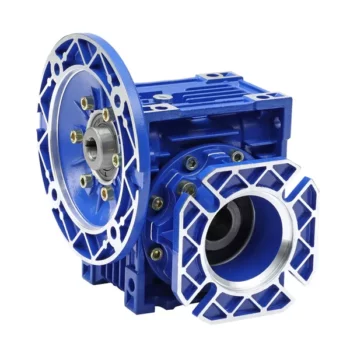
How to Calculate the Input and Output Speeds of a Worm Gearbox?
Calculating the input and output speeds of a worm gearbox involves understanding the gear ratio and the principles of gear reduction. Here’s how you can calculate these speeds:
- Input Speed: The input speed (N1) is the speed of the driving gear, which is the worm gear in this case. It is usually provided by the manufacturer or can be measured directly.
- Output Speed: The output speed (N2) is the speed of the driven gear, which is the worm wheel. To calculate the output speed, use the formula:
N2 = N1 / (Z1 * i)
Where:
N2 = Output speed (rpm)
N1 = Input speed (rpm)
Z1 = Number of teeth on the worm gear
i = Gear ratio (ratio of the number of teeth on the worm gear to the number of threads on the worm)
It’s important to note that worm gearboxes are designed for gear reduction, which means that the output speed is lower than the input speed. Additionally, the efficiency of the gearbox, friction, and other factors can affect the actual output speed. Calculating the input and output speeds is crucial for understanding the performance and capabilities of the worm gearbox in a specific application.
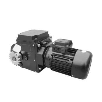
Lubrication Requirements for a Worm Gearbox
Lubrication is crucial for maintaining the performance and longevity of a worm gearbox. Here are the key considerations for lubricating a worm gearbox:
- Type of Lubricant: Use a high-quality, high-viscosity lubricant specifically designed for worm gearboxes. Worm gearboxes require lubricants with additives that provide proper lubrication and prevent wear.
- Lubrication Interval: Follow the manufacturer’s recommendations for lubrication intervals. Regularly check the gearbox’s temperature and oil condition to determine the optimal frequency of lubrication.
- Oil Level: Maintain the proper oil level to ensure effective lubrication. Too little oil can lead to insufficient lubrication, while too much oil can cause overheating and foaming.
- Lubrication Points: Identify all the lubrication points on the gearbox, including the worm and wheel gear surfaces. Apply the lubricant evenly to ensure complete coverage.
- Temperature: Consider the operating temperature of the gearbox. Some lubricants have temperature limits, and extreme temperatures can affect lubricant viscosity and performance.
- Cleanliness: Keep the gearbox and the surrounding area clean to prevent contaminants from entering the lubricant. Use proper filtration and seals to maintain a clean environment.
- Monitoring: Regularly monitor the gearbox’s temperature, noise level, and vibration to detect any signs of inadequate lubrication or other issues.
Proper lubrication will reduce friction, wear, and heat generation, ensuring smooth and efficient operation of the worm gearbox. Always refer to the manufacturer’s guidelines for lubrication specifications and intervals.


editor by CX 2023-09-13
China high quality Hot Selling Industrial Transmission Nmrv Worm Gear Motor Gearbox supplier
Product Description
Product Description
Main Materials:
1)housing:aluminium alloy ADC12(size 571-090); die cast iron HT200(size 110-150);
2)Worm:20Cr, ZI Involute profile; carbonize&quencher heat treatment make gear surface hardness up to 56-62 HRC; After precision grinding, carburization layer’s thickness between 0.3-0.5mm.
3)Worm Wheel:wearable stannum alloy CuSn10-1
Detailed Photos
Combination Options:
Input:with input shaft, With square flange,With IEC standard input flange
Output:with torque arm, output flange, single output shaft, double output shaft, plastic cover
Worm reducers are available with diffferent combinations: NMRV+NMRV, NMRV+NRV, NMRV+PC, NMRV+UDL, NMRV+MOTORS
Exploded View:
Product Parameters
| Old Model |
New Model | Ratio | Center Distance | Power | Input Dia. | Output Dia. | Output Torque | Weight |
| RV571 | 7.5~100 | 25mm | 0.06KW~0.12KW | Φ9 | Φ11 | 21N.m | 0.7kgs | |
| RV030 | RW030 | 7.5~100 | 30mm | 0.06KW~0.25KW | Φ9(Φ11) | Φ14 | 45N.m | 1.2kgs |
| RV040 | RW040 | 7.5~100 | 40mm | 0.09KW~0.55KW | Φ9(Φ11,Φ14) | Φ18(Φ19) | 84N.m | 2.3kgs |
| RV050 | RW050 | 7.5~100 | 50mm | 0.12KW~1.5KW | Φ11(Φ14,Φ19) | Φ25(Φ24) | 160N.m | 3.5kgs |
| RV063 | RW063 | 7.5~100 | 63mm | 0.18KW~2.2KW | Φ14(Φ19,Φ24) | Φ25(Φ28) | 230N.m | 6.2kgs |
| RV075 | RW075 | 7.5~100 | 75mm | 0.25KW~4.0KW | Φ14(Φ19,Φ24,Φ28) | Φ28(Φ35) | 410N.m | 9.0kgs |
| RV090 | RW090 | 7.5~100 | 90mm | 0.37KW~4.0KW | Φ19(Φ24,Φ28) | Φ35(Φ38) | 725N.m | 13.0kgs |
| RV110 | RW110 | 7.5~100 | 110mm | 0.55KW~7.5KW | Φ19(Φ24,Φ28,Φ38) | Φ42 | 1050N.m | 35.0kgs |
| RV130 | RW130 | 7.5~100 | 130mm | 0.75KW~7.5KW | Φ24(Φ28,Φ38) | Φ45 | 1550N.m | 48.0kgs |
| RV150 | RW150 | 7.5~100 | 150mm | 2.2KW~15KW | Φ28(Φ38,Φ42) | Φ50 | 84.0kgs |
GMRV Outline Dimension:
| GMRV | A | B | C | C1 | D(H8) | E(h8) | F | G | G1 | H | H1 | I | M | N | O | P | Q | R | S | T | BL | β | b | t | V |
| 030 | 80 | 97 | 54 | 44 | 14 | 55 | 32 | 56 | 63 | 65 | 29 | 55 | 40 | 57 | 30 | 75 | 44 | 6.5 | 21 | 5.5 | M6*10(n=4) | 0° | 5 | 16.3 | 27 |
| 040 | 100 | 121.5 | 70 | 60 | 18(19) | 60 | 43 | 71 | 78 | 75 | 36.5 | 70 | 50 | 71.5 | 40 | 87 | 55 | 6.5 | 26 | 6.5 | M6*10(n=4) | 45° | 6 | 20.8(21.8) | 35 |
| 050 | 120 | 144 | 80 | 70 | 25(24) | 70 | 49 | 85 | 92 | 85 | 43.5 | 80 | 60 | 84 | 50 | 100 | 64 | 8.5 | 30 | 7 | M8*12(n=4) | 45° | 8 | 28.3(27.3) | 40 |
| 063 | 144 | 174 | 100 | 85 | 25(28) | 80 | 67 | 103 | 112 | 95 | 53 | 95 | 72 | 102 | 63 | 110 | 80 | 8.5 | 36 | 8 | M8*12(n=8) | 45° | 8 | 28.3(31.3) | 50 |
| 075 | 172 | 205 | 120 | 90 | 28(35) | 95 | 72 | 112 | 120 | 115 | 57 | 112.5 | 86 | 119 | 75 | 140 | 93 | 11 | 40 | 10 | M8*14(n=8) | 45° | 8(10) | 31.3(38.3) | 60 |
| 090 | 206 | 238 | 140 | 100 | 35(38) | 110 | 74 | 130 | 140 | 130 | 67 | 129.5 | 103 | 135 | 90 | 160 | 102 | 13 | 45 | 11 | M10*16(n=8) | 45° | 10 | 38.3(41.3) | 70 |
| 110 | 255 | 295 | 170 | 115 | 42 | 130 | – | 144 | 155 | 165 | 74 | 160 | 127.5 | 167.5 | 110 | 200 | 125 | 14 | 50 | 14 | M10*18(n=8) | 45° | 12 | 45.3 | 85 |
| 130 | 293 | 335 | 200 | 120 | 45 | 180 | – | 155 | 170 | 215 | 81 | 179 | 146.5 | 187.5 | 130 | 250 | 140 | 16 | 60 | 15 | M12*20(n=8) | 45° | 14 | 48.8 | 100 |
| 150 | 340 | 400 | 240 | 145 | 50 | 180 | – | 185 | 200 | 215 | 96 | 210 | 170 | 230 | 150 | 250 | 180 | 18 | 72.5 | 18 | M12*22(n=8) | 45° | 14 | 53.8 | 120 |
Company Profile
About CHINAMFG Transmission:
We are a professional reducer manufacturer located in HangZhou, ZHangZhoug province.
Our leading products is full range of RV571-150 worm reducers , also supplied GKM hypoid helical gearbox, GRC inline helical gearbox, PC units, UDL Variators and AC Motors, G3 helical gear motor.
Products are widely used for applications such as: foodstuffs, ceramics, packing, chemicals, pharmacy, plastics, paper-making, construction machinery, metallurgic mine, environmental protection engineering, and all kinds of automatic lines, and assembly lines.
With fast delivery, superior after-sales service, advanced producing facility, our products sell well both at home and abroad. We have exported our reducers to Southeast Asia, Eastern Europe and Middle East and so on.Our aim is to develop and innovate on basis of high quality, and create a good reputation for reducers.
Packing information:Plastic Bags+Cartons+Wooden Cases , or on request
We participate Germany Hannver Exhibition-ZheJiang PTC Fair-Turkey Win Eurasia
Logistics
After Sales Service
1.Maintenance Time and Warranty:Within 1 year after receiving goods.
2.Other Service: Including modeling selection guide, installation guide, and problem resolution guide, etc.
FAQ
1.Q:Can you make as per customer drawing?
A: Yes, we offer customized service for customers accordingly. We can use customer’s nameplate for gearboxes.
2.Q:What is your terms of payment ?
A: 30% deposit before production,balance T/T before delivery.
3.Q:Are you a trading company or manufacturer?
A:We are a manufacurer with advanced equipment and experienced workers.
4.Q:What’s your production capacity?
A:8000-9000 PCS/MONTH
5.Q:Free sample is available or not?
A:Yes, we can supply free sample if customer agree to pay for the courier cost
6.Q:Do you have any certificate?
A:Yes, we have CE certificate and SGS certificate report.
Contact information:
Ms Lingel Pan
For any questions just feel free ton contact me. Many thanks for your kind attention to our company!
| Application: | Motor, Machinery, Marine, Agricultural Machinery, Industry |
|---|---|
| Function: | Distribution Power, Change Drive Torque, Speed Changing, Speed Reduction |
| Layout: | Right Angle |
| Hardness: | Hardened Tooth Surface |
| Installation: | Horizontal Type |
| Step: | Double-Step |
| Samples: |
US$ 35/Piece
1 Piece(Min.Order) | |
|---|
| Customization: |
Available
| Customized Request |
|---|
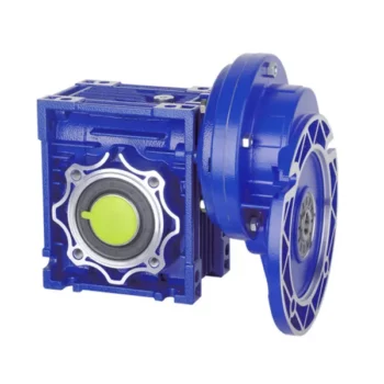
Maintenance Tips for Prolonging the Life of a Worm Gearbox
Proper maintenance is essential to ensure the longevity and reliable performance of a worm gearbox. Here are some maintenance tips to consider:
- Lubrication: Regularly check and replenish the lubricant in the gearbox. Use the recommended lubricant type and quantity specified by the manufacturer.
- Lubrication Schedule: Follow a lubrication schedule based on the operating conditions and manufacturer recommendations. Regular lubrication prevents friction, reduces wear, and dissipates heat.
- Temperature Monitoring: Keep an eye on the operating temperature of the gearbox. Excessive heat can degrade the lubricant and damage components.
- Cleanliness: Keep the gearbox and surrounding area clean from debris and contaminants. Regularly inspect and clean the gearbox exterior.
- Seal Inspection: Check for any leaks or damage to seals and gaskets. Replace them promptly to prevent lubricant leaks and contamination.
- Alignment: Ensure proper alignment between the worm and worm wheel. Misalignment can lead to increased wear and reduced efficiency.
- Torque Monitoring: Monitor the torque levels during operation. Excessive torque can cause overloading and premature wear.
- Regular Inspections: Periodically inspect all components for signs of wear, damage, or unusual noise. Replace worn or damaged parts promptly.
- Proper Usage: Operate the gearbox within its specified limits, including load, speed, and temperature. Avoid overloading or sudden changes in operating conditions.
- Expert Maintenance: If major maintenance or repairs are needed, consult the manufacturer’s guidelines or seek the assistance of qualified technicians.
By following these maintenance tips and adhering to the manufacturer’s recommendations, you can extend the lifespan of your worm gearbox and ensure its optimal performance over time.
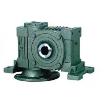
Diagnosing and Fixing Oil Leakage in a Worm Gearbox
Oil leakage in a worm gearbox can lead to reduced lubrication, increased friction, and potential damage to the gearbox components. Here’s a step-by-step process to diagnose and fix oil leakage:
- Inspect the Gearbox: Perform a visual inspection of the gearbox to identify the source of the leakage. Check for oil stains, wet spots, or oil pooling around the gearbox.
- Check Seals and Gaskets: Inspect the seals, gaskets, and O-rings for any signs of wear, cracks, or damage. These components are common points of leakage.
- Tighten Bolts and Fasteners: Ensure that all bolts, screws, and fasteners are properly tightened. Loose fasteners can create gaps that allow oil to escape.
- Replace Damaged Seals: If you find damaged seals or gaskets, replace them with new ones. Use seals that are compatible with the operating conditions and lubricant.
- Check Breather Vent: A clogged or malfunctioning breather vent can cause pressure buildup inside the gearbox, leading to leakage. Clean or replace the breather vent if necessary.
- Examine Shaft Seals: Check the shaft seals for wear or damage. If they’re worn out, replace them with seals of the appropriate size and material.
- Use Proper Lubricant: Ensure that you’re using the correct lubricant recommended for the gearbox. Using the wrong type of lubricant can cause leaks.
- Apply Sealants: In some cases, applying a suitable sealant to the joints and connections can help prevent leaks. Follow the manufacturer’s instructions for proper application.
- Monitor Leakage: After addressing the issues, monitor the gearbox for any signs of continued leakage. If leakage persists, further investigation may be required.
- Regular Maintenance: Implement a regular maintenance schedule that includes checking seals, gaskets, and other potential leakage points. Timely maintenance can prevent future leakage issues.
If you’re unsure about diagnosing or fixing oil leakage in a worm gearbox, consider consulting with a professional or gearbox manufacturer to ensure proper resolution.
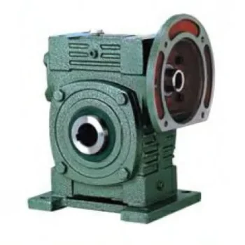
Types of Worm Gear Configurations and Their Uses
Worm gear configurations vary based on the arrangement of the worm and the gear it engages with. Here are common types and their applications:
- Single Enveloping Worm Gear: This configuration offers high torque transmission and efficiency. It’s used in heavy-duty applications like mining equipment and industrial machinery.
- Double Enveloping Worm Gear: With increased contact area, this type provides higher load capacity and improved efficiency. It’s used in aerospace applications, robotics, and precision machinery.
- Non-Throated Worm Gear: This type has a cylindrical worm without a throat. It’s suitable for applications requiring precise motion control, such as CNC machines and robotics.
- Throated Worm Gear: Featuring a throat in the worm, this configuration offers smooth engagement and higher load capacity. It’s used in conveyors, elevators, and automotive applications.
- Non-Modular Worm Gear: In this design, the worm and gear are a matched set, resulting in better meshing and efficiency. It’s utilized in various industries where customization is essential.
- Modular Worm Gear: This type allows interchangeability of worm and gear components, providing flexibility in design and maintenance. It’s commonly used in conveyors, mixers, and material handling systems.
Selecting the appropriate worm gear configuration depends on factors such as load capacity, efficiency, precision, and application requirements. Consulting gearbox experts can help determine the best configuration for your specific needs.


editor by CX 2023-09-13
China high quality 25: 1 Ratio RV 030 50 Vertical Shaft Motor Worm Gearbox planetary gearbox
Product Description
25:1 Ratio RV 030 50 Vertical Shaft Motor Worm GearBox
Product Description
NMRV 571-150 worm gear box with flange and electric motor
NMRV+NMRV Double Stage Arrangement Reduction Gear Box
RV Series Worm Gearbox
worm speed reducer
nmrv worm gear motor
Detailed Photos
RV Series
Including RV / NMRV / NRV.
Main Characteristic of RV Series Worm Gearbox
RV series worm gear reducer is a new-generation product developed by CHINAMFG on the basis of perfecting WJ series products with a compromise of advanced technology both at home and abroad.
1. High-quality aluminum alloy, light in weight and non-rusting.
2. Large in output torque.
3. Smooth running and low noise,durable in dreadful conditions.
4. High radiation efficiency.
5. Good-looking appearance, durable in service life and small volume.
6. Suitable for omnibearing installation.
Main Materials of RV Series Worm Gearbox
1. Housing: die-cast aluminum alloy(frame size: 571 to 090), cast iron(frame size: 110 to 150).
2. Worm: 20Crm, carbonization quencher heat treatment makes the surface hardness of worm gears up to 56-62 HRX, retain carbonization layer’s thickness between 0.3 and 0.5mm after precise grinding.
3. Worm Wheel: wearable stannum bronze alloy.
| SPEED RATIO | 7.5~100 |
| OUTPUT TORQUE | <1050NM |
| IN POWER | 0.09-11KW |
| MOUNTING TYPE | FOOT-MOUNTED FLANGE-MOUNTED |
Product Parameters
| When working, great load capacity, stable running, low noise with high efficiency. | |||||||
| Gear Box’s Usage Field | |||||||
| 1 | Metallurgy | 11 | Agitator | ||||
| 2 | Mine | 12 | Rotary weeder | ||||
| 3 | Machine | 13 | Metallurgy | ||||
| 4 | Energy | 14 | Compressor | ||||
| 5 | Transmission | 15 | Petroleum industry | ||||
| 6 | Water Conserbancy | 16 | Air Compressor | ||||
| 7 | Tomacco | 17 | Crusher | ||||
| 8 | Medical | 18 | Materials | ||||
| 9 | Packing | 19 | Electronics | ||||
| 10 | Chemical industry | 20 | Textile indutry | ||||
| … | … | ||||||
| Power | 0.06kw | 0.09kw | 0.12kw | 0.18kw | 0.25kw | 0.37kw | 0.55kw |
| 0.75kw | 1.1kw | 1.5kw | 2.2kw | 3kw | 4kw | 5.5kw | |
| 7.5kw | 11kw | 15kw | |||||
| Torque | 2.6N.m-3000N.m | ||||||
| Ratio | 7.5-100, the double gearbox is more | ||||||
| Color | Blue, Silver or as customers’ need | ||||||
| Material | Iron or Aluminium | ||||||
| Packing | Carton with Plywood Case or as clients’ requirement | ||||||
| Type | RV571 | RV030 | RV040 | RV050 | RV063 | RV075 | RV090 |
| Weight | 0.7kg | 1.3kg | 2.3kg | 3.5kg | 6.2kg | 9kg | 13kg |
| Type | RV110 | RV130 | RV150 | ||||
| Weight | 35kg | 60kg | 84kg | ||||
Certifications
Packaging & Shipping
Company Profile
Our Advantages
FAQ
| Application: | Motor, Machinery |
|---|---|
| Hardness: | Hardened Tooth Surface |
| Installation: | Horizontal Type |
| Layout: | Worm |
| Gear Shape: | Worm |
| Step: | Single-Step |
| Customization: |
Available
| Customized Request |
|---|

Self-Locking Properties in a Worm Gearbox
Yes, worm gearboxes exhibit self-locking properties, which can be advantageous in certain applications. Self-locking refers to the ability of a mechanism to prevent the transmission of motion from the output shaft back to the input shaft when the system is at rest. Worm gearboxes inherently possess self-locking properties due to the unique design of the worm gear and worm wheel.
The self-locking behavior arises from the angle of the helix on the worm shaft. In a properly designed worm gearbox, the helix angle of the worm is such that it creates a mechanical advantage that resists reverse motion. When the gearbox is not actively driven, the friction between the worm threads and the worm wheel teeth creates a locking effect.
This self-locking feature makes worm gearboxes particularly useful in applications where holding a load in position without external power is necessary. For instance, they are commonly used in situations where there’s a need to prevent a mechanism from backdriving, such as in conveyor systems, hoists, and jacks.
However, it’s important to note that while self-locking properties can be beneficial, they also introduce some challenges. The high friction between the worm gear and worm wheel during self-locking can lead to higher wear and heat generation. Additionally, the self-locking effect can reduce the efficiency of the gearbox when it’s actively transmitting motion.
When considering the use of a worm gearbox for a specific application, it’s crucial to carefully analyze the balance between self-locking capabilities and other performance factors to ensure optimal operation.

How to Calculate the Input and Output Speeds of a Worm Gearbox?
Calculating the input and output speeds of a worm gearbox involves understanding the gear ratio and the principles of gear reduction. Here’s how you can calculate these speeds:
- Input Speed: The input speed (N1) is the speed of the driving gear, which is the worm gear in this case. It is usually provided by the manufacturer or can be measured directly.
- Output Speed: The output speed (N2) is the speed of the driven gear, which is the worm wheel. To calculate the output speed, use the formula:
N2 = N1 / (Z1 * i)
Where:
N2 = Output speed (rpm)
N1 = Input speed (rpm)
Z1 = Number of teeth on the worm gear
i = Gear ratio (ratio of the number of teeth on the worm gear to the number of threads on the worm)
It’s important to note that worm gearboxes are designed for gear reduction, which means that the output speed is lower than the input speed. Additionally, the efficiency of the gearbox, friction, and other factors can affect the actual output speed. Calculating the input and output speeds is crucial for understanding the performance and capabilities of the worm gearbox in a specific application.

Lubrication Requirements for a Worm Gearbox
Lubrication is crucial for maintaining the performance and longevity of a worm gearbox. Here are the key considerations for lubricating a worm gearbox:
- Type of Lubricant: Use a high-quality, high-viscosity lubricant specifically designed for worm gearboxes. Worm gearboxes require lubricants with additives that provide proper lubrication and prevent wear.
- Lubrication Interval: Follow the manufacturer’s recommendations for lubrication intervals. Regularly check the gearbox’s temperature and oil condition to determine the optimal frequency of lubrication.
- Oil Level: Maintain the proper oil level to ensure effective lubrication. Too little oil can lead to insufficient lubrication, while too much oil can cause overheating and foaming.
- Lubrication Points: Identify all the lubrication points on the gearbox, including the worm and wheel gear surfaces. Apply the lubricant evenly to ensure complete coverage.
- Temperature: Consider the operating temperature of the gearbox. Some lubricants have temperature limits, and extreme temperatures can affect lubricant viscosity and performance.
- Cleanliness: Keep the gearbox and the surrounding area clean to prevent contaminants from entering the lubricant. Use proper filtration and seals to maintain a clean environment.
- Monitoring: Regularly monitor the gearbox’s temperature, noise level, and vibration to detect any signs of inadequate lubrication or other issues.
Proper lubrication will reduce friction, wear, and heat generation, ensuring smooth and efficient operation of the worm gearbox. Always refer to the manufacturer’s guidelines for lubrication specifications and intervals.


editor by CX 2023-09-13
China manufacturer Industrial Transmission Worm Gear Reduction AC Motor Gearbox RV030-150 supplier
Product Description
Product Description
Main Materials:
1)housing:aluminium alloy ADC12(size 571-090); die cast iron HT200(size 110-150);
2)Worm:20Cr, ZI Involute profile; carbonize&quencher heat treatment make gear surface hardness up to 56-62 HRC; After precision grinding, carburization layer’s thickness between 0.3-0.5mm.
3)Worm Wheel:wearable stannum alloy CuSn10-1
Detailed Photos
Combination Options:
Input:with input shaft, With square flange,With IEC standard input flange
Output:with torque arm, output flange, single output shaft, double output shaft, plastic cover
Worm reducers are available with diffferent combinations: NMRV+NMRV, NMRV+NRV, NMRV+PC, NMRV+UDL, NMRV+MOTORS
Exploded View:
Product Parameters
| Old Model |
New Model | Ratio | Center Distance | Power | Input Dia. | Output Dia. | Output Torque | Weight |
| RV571 | 7.5~100 | 25mm | 0.06KW~0.12KW | Φ9 | Φ11 | 21N.m | 0.7kgs | |
| RV030 | RW030 | 7.5~100 | 30mm | 0.06KW~0.25KW | Φ9(Φ11) | Φ14 | 45N.m | 1.2kgs |
| RV040 | RW040 | 7.5~100 | 40mm | 0.09KW~0.55KW | Φ9(Φ11,Φ14) | Φ18(Φ19) | 84N.m | 2.3kgs |
| RV050 | RW050 | 7.5~100 | 50mm | 0.12KW~1.5KW | Φ11(Φ14,Φ19) | Φ25(Φ24) | 160N.m | 3.5kgs |
| RV063 | RW063 | 7.5~100 | 63mm | 0.18KW~2.2KW | Φ14(Φ19,Φ24) | Φ25(Φ28) | 230N.m | 6.2kgs |
| RV075 | RW075 | 7.5~100 | 75mm | 0.25KW~4.0KW | Φ14(Φ19,Φ24,Φ28) | Φ28(Φ35) | 410N.m | 9.0kgs |
| RV090 | RW090 | 7.5~100 | 90mm | 0.37KW~4.0KW | Φ19(Φ24,Φ28) | Φ35(Φ38) | 725N.m | 13.0kgs |
| RV110 | RW110 | 7.5~100 | 110mm | 0.55KW~7.5KW | Φ19(Φ24,Φ28,Φ38) | Φ42 | 1050N.m | 35.0kgs |
| RV130 | RW130 | 7.5~100 | 130mm | 0.75KW~7.5KW | Φ24(Φ28,Φ38) | Φ45 | 1550N.m | 48.0kgs |
| RV150 | RW150 | 7.5~100 | 150mm | 2.2KW~15KW | Φ28(Φ38,Φ42) | Φ50 | 84.0kgs |
GMRV Outline Dimension:
| GMRV | A | B | C | C1 | D(H8) | E(h8) | F | G | G1 | H | H1 | I | M | N | O | P | Q | R | S | T | BL | β | b | t | V |
| 030 | 80 | 97 | 54 | 44 | 14 | 55 | 32 | 56 | 63 | 65 | 29 | 55 | 40 | 57 | 30 | 75 | 44 | 6.5 | 21 | 5.5 | M6*10(n=4) | 0° | 5 | 16.3 | 27 |
| 040 | 100 | 121.5 | 70 | 60 | 18(19) | 60 | 43 | 71 | 78 | 75 | 36.5 | 70 | 50 | 71.5 | 40 | 87 | 55 | 6.5 | 26 | 6.5 | M6*10(n=4) | 45° | 6 | 20.8(21.8) | 35 |
| 050 | 120 | 144 | 80 | 70 | 25(24) | 70 | 49 | 85 | 92 | 85 | 43.5 | 80 | 60 | 84 | 50 | 100 | 64 | 8.5 | 30 | 7 | M8*12(n=4) | 45° | 8 | 28.3(27.3) | 40 |
| 063 | 144 | 174 | 100 | 85 | 25(28) | 80 | 67 | 103 | 112 | 95 | 53 | 95 | 72 | 102 | 63 | 110 | 80 | 8.5 | 36 | 8 | M8*12(n=8) | 45° | 8 | 28.3(31.3) | 50 |
| 075 | 172 | 205 | 120 | 90 | 28(35) | 95 | 72 | 112 | 120 | 115 | 57 | 112.5 | 86 | 119 | 75 | 140 | 93 | 11 | 40 | 10 | M8*14(n=8) | 45° | 8(10) | 31.3(38.3) | 60 |
| 090 | 206 | 238 | 140 | 100 | 35(38) | 110 | 74 | 130 | 140 | 130 | 67 | 129.5 | 103 | 135 | 90 | 160 | 102 | 13 | 45 | 11 | M10*16(n=8) | 45° | 10 | 38.3(41.3) | 70 |
| 110 | 255 | 295 | 170 | 115 | 42 | 130 | – | 144 | 155 | 165 | 74 | 160 | 127.5 | 167.5 | 110 | 200 | 125 | 14 | 50 | 14 | M10*18(n=8) | 45° | 12 | 45.3 | 85 |
| 130 | 293 | 335 | 200 | 120 | 45 | 180 | – | 155 | 170 | 215 | 81 | 179 | 146.5 | 187.5 | 130 | 250 | 140 | 16 | 60 | 15 | M12*20(n=8) | 45° | 14 | 48.8 | 100 |
| 150 | 340 | 400 | 240 | 145 | 50 | 180 | – | 185 | 200 | 215 | 96 | 210 | 170 | 230 | 150 | 250 | 180 | 18 | 72.5 | 18 | M12*22(n=8) | 45° | 14 | 53.8 | 120 |
Company Profile
About CHINAMFG Transmission:
We are a professional reducer manufacturer located in HangZhou, ZHangZhoug province.
Our leading products is full range of RV571-150 worm reducers , also supplied GKM hypoid helical gearbox, GRC inline helical gearbox, PC units, UDL Variators and AC Motors, G3 helical gear motor.
Products are widely used for applications such as: foodstuffs, ceramics, packing, chemicals, pharmacy, plastics, paper-making, construction machinery, metallurgic mine, environmental protection engineering, and all kinds of automatic lines, and assembly lines.
With fast delivery, superior after-sales service, advanced producing facility, our products sell well both at home and abroad. We have exported our reducers to Southeast Asia, Eastern Europe and Middle East and so on.Our aim is to develop and innovate on basis of high quality, and create a good reputation for reducers.
Packing information:Plastic Bags+Cartons+Wooden Cases , or on request
We participate Germany Hannver Exhibition-ZheJiang PTC Fair-Turkey Win Eurasia
Logistics
After Sales Service
1.Maintenance Time and Warranty:Within 1 year after receiving goods.
2.Other Service: Including modeling selection guide, installation guide, and problem resolution guide, etc.
FAQ
1.Q:Can you make as per customer drawing?
A: Yes, we offer customized service for customers accordingly. We can use customer’s nameplate for gearboxes.
2.Q:What is your terms of payment ?
A: 30% deposit before production,balance T/T before delivery.
3.Q:Are you a trading company or manufacturer?
A:We are a manufacurer with advanced equipment and experienced workers.
4.Q:What’s your production capacity?
A:8000-9000 PCS/MONTH
5.Q:Free sample is available or not?
A:Yes, we can supply free sample if customer agree to pay for the courier cost
6.Q:Do you have any certificate?
A:Yes, we have CE certificate and SGS certificate report.
Contact information:
Ms Lingel Pan
For any questions just feel free ton contact me. Many thanks for your kind attention to our company!
| Application: | Motor, Machinery, Marine, Agricultural Machinery, Industry |
|---|---|
| Function: | Distribution Power, Change Drive Torque, Speed Changing, Speed Reduction |
| Layout: | Right Angle |
| Hardness: | Hardened Tooth Surface |
| Installation: | Horizontal Type |
| Step: | Double-Step |
| Samples: |
US$ 35/Piece
1 Piece(Min.Order) | |
|---|
| Customization: |
Available
| Customized Request |
|---|

Maintenance Tips for Prolonging the Life of a Worm Gearbox
Proper maintenance is essential to ensure the longevity and reliable performance of a worm gearbox. Here are some maintenance tips to consider:
- Lubrication: Regularly check and replenish the lubricant in the gearbox. Use the recommended lubricant type and quantity specified by the manufacturer.
- Lubrication Schedule: Follow a lubrication schedule based on the operating conditions and manufacturer recommendations. Regular lubrication prevents friction, reduces wear, and dissipates heat.
- Temperature Monitoring: Keep an eye on the operating temperature of the gearbox. Excessive heat can degrade the lubricant and damage components.
- Cleanliness: Keep the gearbox and surrounding area clean from debris and contaminants. Regularly inspect and clean the gearbox exterior.
- Seal Inspection: Check for any leaks or damage to seals and gaskets. Replace them promptly to prevent lubricant leaks and contamination.
- Alignment: Ensure proper alignment between the worm and worm wheel. Misalignment can lead to increased wear and reduced efficiency.
- Torque Monitoring: Monitor the torque levels during operation. Excessive torque can cause overloading and premature wear.
- Regular Inspections: Periodically inspect all components for signs of wear, damage, or unusual noise. Replace worn or damaged parts promptly.
- Proper Usage: Operate the gearbox within its specified limits, including load, speed, and temperature. Avoid overloading or sudden changes in operating conditions.
- Expert Maintenance: If major maintenance or repairs are needed, consult the manufacturer’s guidelines or seek the assistance of qualified technicians.
By following these maintenance tips and adhering to the manufacturer’s recommendations, you can extend the lifespan of your worm gearbox and ensure its optimal performance over time.
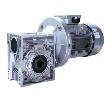
Does a Worm Reducer Require Frequent Maintenance?
Worm reducers generally require less frequent maintenance compared to some other types of gearboxes due to their design and operating characteristics. However, maintenance is still essential to ensure optimal performance and longevity. Here are some key points to consider:
- Lubrication: Proper lubrication is crucial for worm gearboxes. Regularly check the lubricant level and quality to prevent wear and overheating. Lubricant should be changed as recommended by the manufacturer.
- Inspections: Periodically inspect the gearbox for signs of wear, damage, or oil leaks. Check for any unusual noises, vibrations, or changes in performance that could indicate a problem.
- Tightening and Alignment: Check and tighten any loose fasteners and ensure that the gearbox is properly aligned. Misalignment can lead to increased wear and reduced efficiency.
- Seal Maintenance: Inspect and maintain seals to prevent oil leakage and contaminants from entering the gearbox.
- Cleaning: Keep the gearbox clean from debris and contaminants that could affect its performance. Regular cleaning can prevent premature wear and damage.
- Load and Speed: Ensure that the gearbox is operating within its rated load and speed limits. Exceeding these limits can lead to accelerated wear and potential failure.
- Environmental Conditions: Consider the operating environment of the gearbox. Extreme temperatures, humidity, and other factors can impact the gearbox’s performance and longevity.
While worm gearboxes are known for their durability and self-locking feature, neglecting maintenance can lead to premature wear, reduced efficiency, and potential breakdowns. Following the manufacturer’s recommendations for maintenance intervals and procedures is essential to keep the worm reducer in optimal condition.

Preventing Backlash in a Worm Gearbox
Backlash in a worm gearbox can lead to reduced accuracy, positioning errors, and decreased overall efficiency. Here are steps to prevent or minimize backlash:
- High-Quality Components: Use high-quality worm gears and worm wheels with tight manufacturing tolerances. Precision components will help reduce backlash.
- Proper Meshing: Ensure the worm gear and worm wheel are properly aligned and meshed. Improper meshing can lead to increased backlash.
- Preload: Applying a small amount of preload to the worm gear can help reduce backlash. However, excessive preload can increase friction and wear.
- Anti-Backlash Mechanisms: Consider using anti-backlash mechanisms, such as spring-loaded systems or adjustable shims, to compensate for any inherent backlash.
- Lubrication: Proper lubrication can reduce friction and play a role in minimizing backlash. Use a lubricant that provides good film strength and reduces wear.
- Maintenance: Regularly inspect and maintain the gearbox to identify and address any changes in backlash over time.
It’s important to strike a balance between reducing backlash and maintaining smooth operation. Consulting with gearbox experts and following manufacturer guidelines will help you optimize your worm gearbox’s performance while minimizing backlash.


editor by CX 2023-09-13
China high quality Hot Selling Skm Series Electric Motor Worm Gear Transmission Reduction Gearbox for Sale bevel gearbox
Product Description
Recommended by seller
Technical features
The high degree of modularity is a design feature of SKM.SKB series helical-hypoid gear unit. It can be connected respectively with motors such as normal motor, brake motor, explosion-proof motor, frequency conversion motor, servo motor, IEC motor and so on. This kind of product is widely used in drive fields such as textile, footstuff, ceramice packing, logistic, plastics and so on
Product Parameters
|
Applicable Industries |
Garment Shops, Manufacturing Plant, Machinery Repair Shops, Food & Beverage Factory |
|
Gearing Arrangement |
Hypoid |
|
Output Torque |
100~500NM |
|
Input Speed |
1400rpm |
|
Output Speed |
5~187 |
|
Place of Origin |
China |
|
Brand Name |
HUAKE |
|
Product name |
Hypoid gear reducer |
|
Color |
Blue |
|
Ratio |
5-400 |
|
Certificate |
ISO9001 CCC CE |
Products characteristics
SKM SKB Series helical gear units has more than 4 types, power 0.12-4kw, ratio 7.73-302.5, torque max 100-500NM, Modulaw and multistructure can meet the demands of various conditions.
(1) Ground-hardened helical gears.
(2) Modularity, can be combined in many forms
(3) Made of high-quality aluminum alloy, light in weight and nonrusting
(4)Large in output torque, high efficiencym energy saving and environmental protection
(5) The mounting dimension of SKM series are compatible with SMRV series worm gear unit
(A part of SMRV050 dimensions are different from SKM28)
(6) The mounting dimension of SKB series are compatible with W series worm gear unit.
Features&Specification
SKM28B~SKM58B:2-Stage hypoid helical gear units. Speed ratio range7.48~60.5 SKM28C~SKM58C:3-Stage hypoid helical gear units. Speed ratio range:4918~302.5 One of the features of the hypoid gear speed reducer is that the shafts intersect at 2 mutually parallel planes,providing greater torque in the same construction space than an ordinary helical gear reducer. And its strength is much higher than that of worm gear reducer. 1.Omnidirectional mounting 2.Housing made of high-quality aluminum alloydie-casting,light weight good rust resistance 3.Low back clearance 4.Smooth transmission and low noise 5.Customized products available
For more models, please contact us!
F helical gear reducer
Parallel output, compact structure, large transmission torque, stable operation, low noise and long life.
Installation method: base installation, flange installation, torque arm installation.
Reduction ratio: basic type 2 level 4.3-25.3, 3 level 28.2-273, combined to 18509.
The rotation direction of the input and output of the basic two-stage is the same, and the three-stage is opposite; please consult when combining.
Output mode: hollow shaft output or CHINAMFG shaft output.
Average efficiency: Level 2 96%, Level 3 94%, F/CR average efficiency 85%.
K helical bevel gear reducer
Vertical output, compact structure, hard tooth surface transmission torque, high-precision gears ensure stable work, low noise
and long life.
Installation method: base installation, flange installation, torque arm installation, small flange installation.
Input mode: motor direct connection, motor belt connection or input shaft, connection flange input.
Output mode: hollow shaft output or CHINAMFG shaft output, the average efficiency is 94%.
Reduction ratio: basic type 8.1-191, combined to 13459.
R helical gear reducer
Small bias output, compact structure, maximum use of cabinet space, the second and third levels are in the same cabinet. Using an integral cast box, the box structure has good rigidity, which is easy to improve the strength of the shaft and the life of the
bearing.
Installation method: pedestal installation, flanges with large and small flanges are easy to choose.
Solid shaft output, the average efficiency is 96% in the second stage, 94% in the third stage, and 85% in CR/CR. The CRM series specially designed for mixing can carry large axial and radial forces.
Company Profile
Certifications
Packaging & Shipping
FAQ
| Application: | Motor, Electric Cars, Motorcycle, Machinery, Marine, Toy, Agricultural Machinery, Car, Transmission Parts |
|---|---|
| Function: | Distribution Power, Clutch, Change Drive Torque, Change Drive Direction, Speed Changing, Speed Reduction, Speed Increase |
| Layout: | Cycloidal |
| Hardness: | Hardened Tooth Surface |
| Installation: | Torque Arm Type |
| Step: | Single-Step |
| Samples: |
US$ 80/Piece
1 Piece(Min.Order) | |
|---|
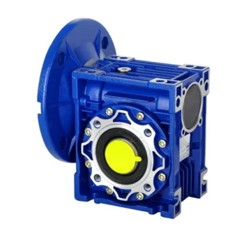
How to Install and Align a Worm Reducer Properly
Proper installation and alignment of a worm reducer are crucial for ensuring optimal performance and longevity. Follow these steps to install and align a worm reducer:
- Preparation: Gather all the necessary tools, equipment, and safety gear before starting the installation process.
- Positioning: Place the worm reducer in the desired location, ensuring that it is securely mounted to a stable surface. Use appropriate fasteners and mounting brackets as needed.
- Shaft Alignment: Check the alignment of the input and output shafts. Use precision measurement tools to ensure that the shafts are parallel and in line with each other.
- Base Plate Alignment: Align the base plate of the reducer with the foundation or mounting surface. Ensure that the base plate is level and properly aligned before securing it in place.
- Bolt Tightening: Gradually and evenly tighten the mounting bolts to the manufacturer’s specifications. This helps ensure proper contact between the reducer and the mounting surface.
- Check for Clearance: Verify that there is enough clearance for any rotating components or parts that may move during operation. Avoid any interference that could cause damage or performance issues.
- Lubrication: Apply the recommended lubricant to the worm reducer according to the manufacturer’s guidelines. Proper lubrication is essential for smooth operation and reducing friction.
- Alignment Testing: After installation, run the worm reducer briefly without a load to check for any unusual noises, vibrations, or misalignment issues.
- Load Testing: Gradually introduce the intended load to the worm reducer and monitor its performance. Ensure that the reducer operates smoothly and efficiently under the load conditions.
It’s important to refer to the manufacturer’s installation guidelines and specifications for your specific worm reducer model. Proper installation and alignment will contribute to the gearbox’s reliability, efficiency, and overall functionality.

How to Calculate the Input and Output Speeds of a Worm Gearbox?
Calculating the input and output speeds of a worm gearbox involves understanding the gear ratio and the principles of gear reduction. Here’s how you can calculate these speeds:
- Input Speed: The input speed (N1) is the speed of the driving gear, which is the worm gear in this case. It is usually provided by the manufacturer or can be measured directly.
- Output Speed: The output speed (N2) is the speed of the driven gear, which is the worm wheel. To calculate the output speed, use the formula:
N2 = N1 / (Z1 * i)
Where:
N2 = Output speed (rpm)
N1 = Input speed (rpm)
Z1 = Number of teeth on the worm gear
i = Gear ratio (ratio of the number of teeth on the worm gear to the number of threads on the worm)
It’s important to note that worm gearboxes are designed for gear reduction, which means that the output speed is lower than the input speed. Additionally, the efficiency of the gearbox, friction, and other factors can affect the actual output speed. Calculating the input and output speeds is crucial for understanding the performance and capabilities of the worm gearbox in a specific application.

Preventing Backlash in a Worm Gearbox
Backlash in a worm gearbox can lead to reduced accuracy, positioning errors, and decreased overall efficiency. Here are steps to prevent or minimize backlash:
- High-Quality Components: Use high-quality worm gears and worm wheels with tight manufacturing tolerances. Precision components will help reduce backlash.
- Proper Meshing: Ensure the worm gear and worm wheel are properly aligned and meshed. Improper meshing can lead to increased backlash.
- Preload: Applying a small amount of preload to the worm gear can help reduce backlash. However, excessive preload can increase friction and wear.
- Anti-Backlash Mechanisms: Consider using anti-backlash mechanisms, such as spring-loaded systems or adjustable shims, to compensate for any inherent backlash.
- Lubrication: Proper lubrication can reduce friction and play a role in minimizing backlash. Use a lubricant that provides good film strength and reduces wear.
- Maintenance: Regularly inspect and maintain the gearbox to identify and address any changes in backlash over time.
It’s important to strike a balance between reducing backlash and maintaining smooth operation. Consulting with gearbox experts and following manufacturer guidelines will help you optimize your worm gearbox’s performance while minimizing backlash.


editor by CX 2023-09-13
China Good quality DC Motor Worm Gearbox for Substitude for Motovario wholesaler
Product Description
SC Transmission Top Quality NNRV/NRV
Worm Gearbox for Substitude for Motovario
Product Description
Features
1. Wide transmission rate, strong output torque
2. Compact mechanical structure, light weight, small volume&Good heat-dissipating
3. Smooth operation with lower noise or vibration
4. Easy mounting, free linking, high efficiency
5. PERFECT SUBSTITUDE FOR MOTOVARIO AND CHINAMFG PRODUCTS
Detailed Photos
Product Parameters
Company Profile
FAQ
Shipping
| Application: | Motor, Machinery, Agricultural Machinery |
|---|---|
| Gear Shape: | Bevel Gear |
| Type: | Worm Reducer |
| Input Power: | 0.1-25.8kw |
| Color: | Depend on Customer/Blue/ Silver White/Grey |
| Motor: | Can Be Matched with The Motor |
| Samples: |
US$ 50/Piece
1 Piece(Min.Order) | |
|---|
| Customization: |
Available
| Customized Request |
|---|
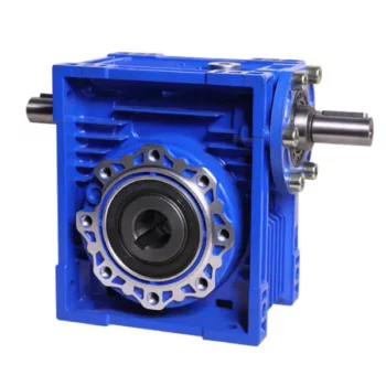
Can a Worm Gearbox be Used for High-Speed Applications?
Worm gearboxes are generally not recommended for high-speed applications due to their inherent design characteristics. Here’s why:
- Efficiency: Worm gearboxes tend to have lower efficiency compared to other gearbox types, which means they can generate more heat and experience more energy loss at high speeds.
- Heat Generation: The sliding contact between the worm and worm wheel in a worm gearbox can lead to significant friction and heat generation, especially at high speeds. This heat can cause thermal expansion, affecting the gearbox’s performance and longevity.
- Wear and Noise: High speeds can exacerbate wear and noise issues in worm gearboxes. Increased friction and wear can lead to faster degradation of components, resulting in reduced lifespan and increased maintenance needs.
- Backlash: Worm gearboxes may have higher backlash compared to other gearbox types, which can impact precision and accuracy in high-speed applications.
While worm gearboxes are more commonly used in applications requiring high torque and moderate speeds, they may not be the best choice for high-speed scenarios. If high-speed operation is a requirement, other gearbox types such as helical, spur, or planetary gearboxes are often better suited due to their higher efficiency, lower heat generation, and reduced wear at elevated speeds.

Energy Efficiency of a Worm Gearbox: What to Expect
The energy efficiency of a worm gearbox is an important factor to consider when evaluating its performance. Here’s what you can expect in terms of energy efficiency:
- Typical Efficiency Range: Worm gearboxes are known for their compact size and high gear reduction capabilities, but they can exhibit lower energy efficiency compared to other types of gearboxes. The efficiency of a worm gearbox typically falls in the range of 50% to 90%, depending on various factors such as design, manufacturing quality, lubrication, and load conditions.
- Inherent Losses: Worm gearboxes inherently involve sliding contact between the worm and worm wheel. This sliding contact generates friction, leading to energy losses in the form of heat. The sliding action also contributes to lower efficiency when compared to gearboxes with rolling contact.
- Helical-Worm Design: Some manufacturers offer helical-worm gearbox designs that combine elements of helical and worm gearing. These designs aim to improve efficiency by incorporating helical gears in the reduction stage, which can lead to higher efficiency compared to traditional worm gearboxes.
- Lubrication: Proper lubrication plays a significant role in minimizing friction and improving energy efficiency. Using high-quality lubricants and ensuring the gearbox is adequately lubricated can help reduce losses due to friction.
- Application Considerations: While worm gearboxes might have lower energy efficiency compared to other types of gearboxes, they still offer advantages in terms of compactness, high torque transmission, and simplicity. Therefore, the decision to use a worm gearbox should consider the specific requirements of the application, including the trade-off between energy efficiency and other performance factors.
When selecting a worm gearbox, it’s essential to consider the trade-offs between energy efficiency, torque transmission, gearbox size, and the specific needs of the application. Regular maintenance, proper lubrication, and selecting a well-designed gearbox can contribute to achieving the best possible energy efficiency within the limitations of worm gearbox technology.
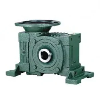
What Industries Commonly Use Worm Reducers?
Worm reducers are versatile mechanical components that find applications in various industries due to their unique advantages and capabilities. Some of the industries that commonly use worm reducers include:
- Material Handling: Worm reducers are widely used in material handling equipment such as conveyors, bucket elevators, and cranes to control movement and manage heavy loads.
- Automotive: They are utilized in automotive manufacturing processes, assembly lines, and vehicle positioning systems.
- Food and Beverage: Worm reducers are used in food processing and packaging machinery where hygiene and cleanliness are crucial.
- Agriculture: Agricultural equipment like irrigation systems and tractors use worm reducers for controlling rotational motion.
- Mining and Construction: Heavy-duty applications in mining equipment, excavators, and construction machinery benefit from the torque multiplication provided by worm reducers.
- Energy: Wind turbines and solar tracking systems use worm reducers to convert low-speed, high-torque motion into rotational energy.
- Textile: Textile machinery employs worm reducers for controlling speed and tension in weaving and spinning operations.
- Packaging: Packaging equipment relies on worm reducers for precise movement and positioning of packaging materials.
- Medical: Medical devices and equipment often utilize worm reducers for their accuracy and controlled motion.
- Printing: Printing machines use worm reducers to regulate paper feed and ensure consistent printing quality.
Worm reducers’ ability to provide high torque output, compact design, and self-locking characteristics makes them suitable for applications requiring reliable and controlled motion across various industries.


editor by CX 2023-09-13
China high quality Nmrv025-150 Hollow Shaft Speed Reducer Worm Gearbox for AC Motor gearbox adjustment
Product Description
Product Description
Main Materials:
1)housing:aluminium alloy ADC12(size 571-090); die cast iron HT200(size 110-150);
2)Worm:20Cr, ZI Involute profile; carbonize&quencher heat treatment make gear surface hardness up to 56-62 HRC; After precision grinding, carburization layer’s thickness between 0.3-0.5mm.
3)Worm Wheel:wearable stannum alloy CuSn10-1
Detailed Photos
Combination Options:
Input:with input shaft, With square flange,With IEC standard input flange
Output:with torque arm, output flange, single output shaft, double output shaft, plastic cover
Worm reducers are available with diffferent combinations: NMRV+NMRV, NMRV+NRV, NMRV+PC, NMRV+UDL, NMRV+MOTORS
Exploded View:
Product Parameters
| Old Model |
New Model | Ratio | Center Distance | Power | Input Dia. | Output Dia. | Output Torque | Weight |
| RV571 | 7.5~100 | 25mm | 0.06KW~0.12KW | Φ9 | Φ11 | 21N.m | 0.7kgs | |
| RV030 | RW030 | 7.5~100 | 30mm | 0.06KW~0.25KW | Φ9(Φ11) | Φ14 | 45N.m | 1.2kgs |
| RV040 | RW040 | 7.5~100 | 40mm | 0.09KW~0.55KW | Φ9(Φ11,Φ14) | Φ18(Φ19) | 84N.m | 2.3kgs |
| RV050 | RW050 | 7.5~100 | 50mm | 0.12KW~1.5KW | Φ11(Φ14,Φ19) | Φ25(Φ24) | 160N.m | 3.5kgs |
| RV063 | RW063 | 7.5~100 | 63mm | 0.18KW~2.2KW | Φ14(Φ19,Φ24) | Φ25(Φ28) | 230N.m | 6.2kgs |
| RV075 | RW075 | 7.5~100 | 75mm | 0.25KW~4.0KW | Φ14(Φ19,Φ24,Φ28) | Φ28(Φ35) | 410N.m | 9.0kgs |
| RV090 | RW090 | 7.5~100 | 90mm | 0.37KW~4.0KW | Φ19(Φ24,Φ28) | Φ35(Φ38) | 725N.m | 13.0kgs |
| RV110 | RW110 | 7.5~100 | 110mm | 0.55KW~7.5KW | Φ19(Φ24,Φ28,Φ38) | Φ42 | 1050N.m | 35.0kgs |
| RV130 | RW130 | 7.5~100 | 130mm | 0.75KW~7.5KW | Φ24(Φ28,Φ38) | Φ45 | 1550N.m | 48.0kgs |
| RV150 | RW150 | 7.5~100 | 150mm | 2.2KW~15KW | Φ28(Φ38,Φ42) | Φ50 | 84.0kgs |
GMRV Outline Dimension:
| GMRV | A | B | C | C1 | D(H8) | E(h8) | F | G | G1 | H | H1 | I | M | N | O | P | Q | R | S | T | BL | β | b | t | V |
| 030 | 80 | 97 | 54 | 44 | 14 | 55 | 32 | 56 | 63 | 65 | 29 | 55 | 40 | 57 | 30 | 75 | 44 | 6.5 | 21 | 5.5 | M6*10(n=4) | 0° | 5 | 16.3 | 27 |
| 040 | 100 | 121.5 | 70 | 60 | 18(19) | 60 | 43 | 71 | 78 | 75 | 36.5 | 70 | 50 | 71.5 | 40 | 87 | 55 | 6.5 | 26 | 6.5 | M6*10(n=4) | 45° | 6 | 20.8(21.8) | 35 |
| 050 | 120 | 144 | 80 | 70 | 25(24) | 70 | 49 | 85 | 92 | 85 | 43.5 | 80 | 60 | 84 | 50 | 100 | 64 | 8.5 | 30 | 7 | M8*12(n=4) | 45° | 8 | 28.3(27.3) | 40 |
| 063 | 144 | 174 | 100 | 85 | 25(28) | 80 | 67 | 103 | 112 | 95 | 53 | 95 | 72 | 102 | 63 | 110 | 80 | 8.5 | 36 | 8 | M8*12(n=8) | 45° | 8 | 28.3(31.3) | 50 |
| 075 | 172 | 205 | 120 | 90 | 28(35) | 95 | 72 | 112 | 120 | 115 | 57 | 112.5 | 86 | 119 | 75 | 140 | 93 | 11 | 40 | 10 | M8*14(n=8) | 45° | 8(10) | 31.3(38.3) | 60 |
| 090 | 206 | 238 | 140 | 100 | 35(38) | 110 | 74 | 130 | 140 | 130 | 67 | 129.5 | 103 | 135 | 90 | 160 | 102 | 13 | 45 | 11 | M10*16(n=8) | 45° | 10 | 38.3(41.3) | 70 |
| 110 | 255 | 295 | 170 | 115 | 42 | 130 | – | 144 | 155 | 165 | 74 | 160 | 127.5 | 167.5 | 110 | 200 | 125 | 14 | 50 | 14 | M10*18(n=8) | 45° | 12 | 45.3 | 85 |
| 130 | 293 | 335 | 200 | 120 | 45 | 180 | – | 155 | 170 | 215 | 81 | 179 | 146.5 | 187.5 | 130 | 250 | 140 | 16 | 60 | 15 | M12*20(n=8) | 45° | 14 | 48.8 | 100 |
| 150 | 340 | 400 | 240 | 145 | 50 | 180 | – | 185 | 200 | 215 | 96 | 210 | 170 | 230 | 150 | 250 | 180 | 18 | 72.5 | 18 | M12*22(n=8) | 45° | 14 | 53.8 | 120 |
Company Profile
About CHINAMFG Transmission:
We are a professional reducer manufacturer located in HangZhou, ZHangZhoug province.
Our leading products is full range of RV571-150 worm reducers , also supplied GKM hypoid helical gearbox, GRC inline helical gearbox, PC units, UDL Variators and AC Motors, G3 helical gear motor.
Products are widely used for applications such as: foodstuffs, ceramics, packing, chemicals, pharmacy, plastics, paper-making, construction machinery, metallurgic mine, environmental protection engineering, and all kinds of automatic lines, and assembly lines.
With fast delivery, superior after-sales service, advanced producing facility, our products sell well both at home and abroad. We have exported our reducers to Southeast Asia, Eastern Europe and Middle East and so on.Our aim is to develop and innovate on basis of high quality, and create a good reputation for reducers.
Packing information:Plastic Bags+Cartons+Wooden Cases , or on request
We participate Germany Hannver Exhibition-ZheJiang PTC Fair-Turkey Win Eurasia
Logistics
After Sales Service
1.Maintenance Time and Warranty:Within 1 year after receiving goods.
2.Other Service: Including modeling selection guide, installation guide, and problem resolution guide, etc.
FAQ
1.Q:Can you make as per customer drawing?
A: Yes, we offer customized service for customers accordingly. We can use customer’s nameplate for gearboxes.
2.Q:What is your terms of payment ?
A: 30% deposit before production,balance T/T before delivery.
3.Q:Are you a trading company or manufacturer?
A:We are a manufacurer with advanced equipment and experienced workers.
4.Q:What’s your production capacity?
A:8000-9000 PCS/MONTH
5.Q:Free sample is available or not?
A:Yes, we can supply free sample if customer agree to pay for the courier cost
6.Q:Do you have any certificate?
A:Yes, we have CE certificate and SGS certificate report.
Contact information:
Ms Lingel Pan
For any questions just feel free ton contact me. Many thanks for your kind attention to our company!
| Application: | Motor, Machinery, Marine, Agricultural Machinery, Industry |
|---|---|
| Function: | Distribution Power, Change Drive Torque, Speed Changing, Speed Reduction |
| Layout: | Right Angle |
| Hardness: | Hardened Tooth Surface |
| Installation: | Horizontal Type |
| Step: | Double-Step |
| Samples: |
US$ 10/Piece
1 Piece(Min.Order) | |
|---|
| Customization: |
Available
| Customized Request |
|---|
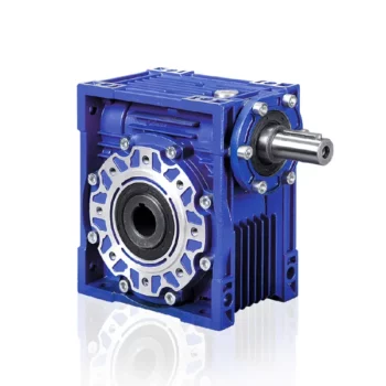
Is it Possible to Reverse the Direction of a Worm Gearbox?
Yes, it is possible to reverse the direction of a worm gearbox by changing the orientation of either the input or output shaft. However, reversing the direction of a worm gearbox can have some implications that need to be considered:
- Efficiency: Reversing the direction of a worm gearbox can potentially affect its efficiency. Worm gearboxes are typically more efficient in one direction of rotation due to the design of the worm and worm wheel.
- Backlash: Reversing the direction of rotation might lead to increased backlash or play in the gearbox, which can impact precision and smooth operation.
- Lubrication: Depending on the gearbox’s design, reversing the direction could affect lubrication distribution and lead to uneven wear on the gear teeth.
- Load: Reversing the direction might also impact the gearbox’s load-carrying capacity, especially if it’s designed for predominantly one-way operation.
- Noise and Vibration: Direction reversal can sometimes result in increased noise and vibration due to changes in gear engagement and meshing behavior.
If you need to reverse the direction of a worm gearbox, it’s advisable to consult the gearbox manufacturer’s guidelines and recommendations. They can provide insights into whether the specific gearbox model is suitable for reversible operation and any precautions or adjustments needed to ensure proper functioning.

Energy Efficiency of a Worm Gearbox: What to Expect
The energy efficiency of a worm gearbox is an important factor to consider when evaluating its performance. Here’s what you can expect in terms of energy efficiency:
- Typical Efficiency Range: Worm gearboxes are known for their compact size and high gear reduction capabilities, but they can exhibit lower energy efficiency compared to other types of gearboxes. The efficiency of a worm gearbox typically falls in the range of 50% to 90%, depending on various factors such as design, manufacturing quality, lubrication, and load conditions.
- Inherent Losses: Worm gearboxes inherently involve sliding contact between the worm and worm wheel. This sliding contact generates friction, leading to energy losses in the form of heat. The sliding action also contributes to lower efficiency when compared to gearboxes with rolling contact.
- Helical-Worm Design: Some manufacturers offer helical-worm gearbox designs that combine elements of helical and worm gearing. These designs aim to improve efficiency by incorporating helical gears in the reduction stage, which can lead to higher efficiency compared to traditional worm gearboxes.
- Lubrication: Proper lubrication plays a significant role in minimizing friction and improving energy efficiency. Using high-quality lubricants and ensuring the gearbox is adequately lubricated can help reduce losses due to friction.
- Application Considerations: While worm gearboxes might have lower energy efficiency compared to other types of gearboxes, they still offer advantages in terms of compactness, high torque transmission, and simplicity. Therefore, the decision to use a worm gearbox should consider the specific requirements of the application, including the trade-off between energy efficiency and other performance factors.
When selecting a worm gearbox, it’s essential to consider the trade-offs between energy efficiency, torque transmission, gearbox size, and the specific needs of the application. Regular maintenance, proper lubrication, and selecting a well-designed gearbox can contribute to achieving the best possible energy efficiency within the limitations of worm gearbox technology.
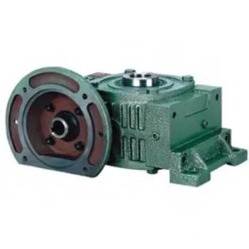
Can a Worm Gearbox Provide High Torque Output?
Yes, a worm gearbox is capable of providing high torque output due to its unique design and principle of operation. Worm gears are known for their high torque multiplication capabilities, making them suitable for applications that require significant torque transfer.
The torque output of a worm gearbox is influenced by several factors:
- Lead Angle: The lead angle of the worm affects the mechanical advantage of the gear system. A larger lead angle can result in higher torque output.
- Worm Diameter: A larger diameter worm can offer increased torque output as it provides more contact area with the gear.
- Gear Ratio: The gear ratio between the worm and the gear determines the torque multiplication factor. A higher gear ratio leads to higher torque output.
- Lubrication: Proper lubrication is essential to minimize friction and ensure efficient torque transmission.
- Material and Quality: High-quality materials and precision manufacturing contribute to the gearbox’s ability to handle high torque loads.
Due to their ability to provide high torque output in a compact form factor, worm gearboxes are commonly used in various industrial applications, including heavy machinery, construction equipment, conveyor systems, and more.


editor by CX 2023-09-13
China OEM Nmrv Worm Gear Transmission Gearbox for Servo Brake Motor car gearbox
Product Description
Product Description
Main Materials:
1)housing:aluminium alloy ADC12(size 571-090); die cast iron HT200(size 110-150);
2)Worm:20Cr, ZI Involute profile; carbonize&quencher heat treatment make gear surface hardness up to 56-62 HRC; After precision grinding, carburization layer’s thickness between 0.3-0.5mm.
3)Worm Wheel:wearable stannum alloy CuSn10-1
Detailed Photos
Combination Options:
Input:with input shaft, With square flange,With IEC standard input flange
Output:with torque arm, output flange, single output shaft, double output shaft, plastic cover
Worm reducers are available with diffferent combinations: NMRV+NMRV, NMRV+NRV, NMRV+PC, NMRV+UDL, NMRV+MOTORS
Exploded View:
Product Parameters
| Old Model |
New Model | Ratio | Center Distance | Power | Input Dia. | Output Dia. | Output Torque | Weight |
| RV571 | 7.5~100 | 25mm | 0.06KW~0.12KW | Φ9 | Φ11 | 21N.m | 0.7kgs | |
| RV030 | RW030 | 7.5~100 | 30mm | 0.06KW~0.25KW | Φ9(Φ11) | Φ14 | 45N.m | 1.2kgs |
| RV040 | RW040 | 7.5~100 | 40mm | 0.09KW~0.55KW | Φ9(Φ11,Φ14) | Φ18(Φ19) | 84N.m | 2.3kgs |
| RV050 | RW050 | 7.5~100 | 50mm | 0.12KW~1.5KW | Φ11(Φ14,Φ19) | Φ25(Φ24) | 160N.m | 3.5kgs |
| RV063 | RW063 | 7.5~100 | 63mm | 0.18KW~2.2KW | Φ14(Φ19,Φ24) | Φ25(Φ28) | 230N.m | 6.2kgs |
| RV075 | RW075 | 7.5~100 | 75mm | 0.25KW~4.0KW | Φ14(Φ19,Φ24,Φ28) | Φ28(Φ35) | 410N.m | 9.0kgs |
| RV090 | RW090 | 7.5~100 | 90mm | 0.37KW~4.0KW | Φ19(Φ24,Φ28) | Φ35(Φ38) | 725N.m | 13.0kgs |
| RV110 | RW110 | 7.5~100 | 110mm | 0.55KW~7.5KW | Φ19(Φ24,Φ28,Φ38) | Φ42 | 1050N.m | 35.0kgs |
| RV130 | RW130 | 7.5~100 | 130mm | 0.75KW~7.5KW | Φ24(Φ28,Φ38) | Φ45 | 1550N.m | 48.0kgs |
| RV150 | RW150 | 7.5~100 | 150mm | 2.2KW~15KW | Φ28(Φ38,Φ42) | Φ50 | 84.0kgs |
GMRV Outline Dimension:
| GMRV | A | B | C | C1 | D(H8) | E(h8) | F | G | G1 | H | H1 | I | M | N | O | P | Q | R | S | T | BL | β | b | t | V |
| 030 | 80 | 97 | 54 | 44 | 14 | 55 | 32 | 56 | 63 | 65 | 29 | 55 | 40 | 57 | 30 | 75 | 44 | 6.5 | 21 | 5.5 | M6*10(n=4) | 0° | 5 | 16.3 | 27 |
| 040 | 100 | 121.5 | 70 | 60 | 18(19) | 60 | 43 | 71 | 78 | 75 | 36.5 | 70 | 50 | 71.5 | 40 | 87 | 55 | 6.5 | 26 | 6.5 | M6*10(n=4) | 45° | 6 | 20.8(21.8) | 35 |
| 050 | 120 | 144 | 80 | 70 | 25(24) | 70 | 49 | 85 | 92 | 85 | 43.5 | 80 | 60 | 84 | 50 | 100 | 64 | 8.5 | 30 | 7 | M8*12(n=4) | 45° | 8 | 28.3(27.3) | 40 |
| 063 | 144 | 174 | 100 | 85 | 25(28) | 80 | 67 | 103 | 112 | 95 | 53 | 95 | 72 | 102 | 63 | 110 | 80 | 8.5 | 36 | 8 | M8*12(n=8) | 45° | 8 | 28.3(31.3) | 50 |
| 075 | 172 | 205 | 120 | 90 | 28(35) | 95 | 72 | 112 | 120 | 115 | 57 | 112.5 | 86 | 119 | 75 | 140 | 93 | 11 | 40 | 10 | M8*14(n=8) | 45° | 8(10) | 31.3(38.3) | 60 |
| 090 | 206 | 238 | 140 | 100 | 35(38) | 110 | 74 | 130 | 140 | 130 | 67 | 129.5 | 103 | 135 | 90 | 160 | 102 | 13 | 45 | 11 | M10*16(n=8) | 45° | 10 | 38.3(41.3) | 70 |
| 110 | 255 | 295 | 170 | 115 | 42 | 130 | – | 144 | 155 | 165 | 74 | 160 | 127.5 | 167.5 | 110 | 200 | 125 | 14 | 50 | 14 | M10*18(n=8) | 45° | 12 | 45.3 | 85 |
| 130 | 293 | 335 | 200 | 120 | 45 | 180 | – | 155 | 170 | 215 | 81 | 179 | 146.5 | 187.5 | 130 | 250 | 140 | 16 | 60 | 15 | M12*20(n=8) | 45° | 14 | 48.8 | 100 |
| 150 | 340 | 400 | 240 | 145 | 50 | 180 | – | 185 | 200 | 215 | 96 | 210 | 170 | 230 | 150 | 250 | 180 | 18 | 72.5 | 18 | M12*22(n=8) | 45° | 14 | 53.8 | 120 |
Company Profile
About CHINAMFG Transmission:
We are a professional reducer manufacturer located in HangZhou, ZHangZhoug province.
Our leading products is full range of RV571-150 worm reducers , also supplied GKM hypoid helical gearbox, GRC inline helical gearbox, PC units, UDL Variators and AC Motors, G3 helical gear motor.
Products are widely used for applications such as: foodstuffs, ceramics, packing, chemicals, pharmacy, plastics, paper-making, construction machinery, metallurgic mine, environmental protection engineering, and all kinds of automatic lines, and assembly lines.
With fast delivery, superior after-sales service, advanced producing facility, our products sell well both at home and abroad. We have exported our reducers to Southeast Asia, Eastern Europe and Middle East and so on.Our aim is to develop and innovate on basis of high quality, and create a good reputation for reducers.
Packing information:Plastic Bags+Cartons+Wooden Cases , or on request
We participate Germany Hannver Exhibition-ZheJiang PTC Fair-Turkey Win Eurasia
Logistics
After Sales Service
1.Maintenance Time and Warranty:Within 1 year after receiving goods.
2.Other Service: Including modeling selection guide, installation guide, and problem resolution guide, etc.
FAQ
1.Q:Can you make as per customer drawing?
A: Yes, we offer customized service for customers accordingly. We can use customer’s nameplate for gearboxes.
2.Q:What is your terms of payment ?
A: 30% deposit before production,balance T/T before delivery.
3.Q:Are you a trading company or manufacturer?
A:We are a manufacurer with advanced equipment and experienced workers.
4.Q:What’s your production capacity?
A:8000-9000 PCS/MONTH
5.Q:Free sample is available or not?
A:Yes, we can supply free sample if customer agree to pay for the courier cost
6.Q:Do you have any certificate?
A:Yes, we have CE certificate and SGS certificate report.
Contact information:
Ms Lingel Pan
For any questions just feel free ton contact me. Many thanks for your kind attention to our company!
| Application: | Motor, Machinery, Marine, Agricultural Machinery, Industry |
|---|---|
| Function: | Distribution Power, Change Drive Torque, Speed Changing, Speed Reduction |
| Layout: | Right Angle |
| Hardness: | Hardened Tooth Surface |
| Installation: | Horizontal Type |
| Step: | Double-Step |
| Samples: |
US$ 12/Piece
1 Piece(Min.Order) | |
|---|
| Customization: |
Available
| Customized Request |
|---|

Is it Possible to Reverse the Direction of a Worm Gearbox?
Yes, it is possible to reverse the direction of a worm gearbox by changing the orientation of either the input or output shaft. However, reversing the direction of a worm gearbox can have some implications that need to be considered:
- Efficiency: Reversing the direction of a worm gearbox can potentially affect its efficiency. Worm gearboxes are typically more efficient in one direction of rotation due to the design of the worm and worm wheel.
- Backlash: Reversing the direction of rotation might lead to increased backlash or play in the gearbox, which can impact precision and smooth operation.
- Lubrication: Depending on the gearbox’s design, reversing the direction could affect lubrication distribution and lead to uneven wear on the gear teeth.
- Load: Reversing the direction might also impact the gearbox’s load-carrying capacity, especially if it’s designed for predominantly one-way operation.
- Noise and Vibration: Direction reversal can sometimes result in increased noise and vibration due to changes in gear engagement and meshing behavior.
If you need to reverse the direction of a worm gearbox, it’s advisable to consult the gearbox manufacturer’s guidelines and recommendations. They can provide insights into whether the specific gearbox model is suitable for reversible operation and any precautions or adjustments needed to ensure proper functioning.

Worm Gearboxes in Conveyor Systems: Benefits and Considerations
Worm gearboxes play a crucial role in conveyor systems, offering several benefits and considerations for their effective integration:
- Space Efficiency: Worm gearboxes have a compact design, making them suitable for applications with limited space, such as conveyor systems.
- High Reduction Ratios: Worm gearboxes can achieve high reduction ratios in a single stage, allowing for slower conveyor speeds without sacrificing torque.
- Self-Locking: Worm gearboxes have inherent self-locking properties, preventing the conveyor from moving when the motor is not actively driving it.
- Directional Control: Worm gearboxes facilitate directional control, enabling the conveyor to move forward or reverse as needed.
- Low Noise: Worm gearboxes often produce lower noise levels compared to other gearbox types, contributing to quieter conveyor operation.
However, there are also considerations to keep in mind when using worm gearboxes in conveyor systems:
- Efficiency: Worm gearboxes may have lower mechanical efficiency compared to some other gearbox types, leading to energy losses.
- Heat Generation: Worm gearboxes can generate more heat due to sliding contact between the worm and gear, necessitating proper cooling mechanisms.
- Lubrication: Proper lubrication is critical to prevent wear and ensure efficient operation. Regular maintenance is required to monitor lubrication levels.
- Load and Speed: Worm gearboxes are well-suited for applications with high torque and low to moderate speed requirements. They may not be optimal for high-speed conveyors.
Before integrating a worm gearbox into a conveyor system, it’s important to carefully consider the specific requirements of the application, including load, speed, space constraints, and efficiency needs. Consulting with gearbox experts and manufacturers can help ensure the right choice for the conveyor’s performance and longevity.
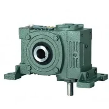
Advantages of Using a Worm Reducer in Mechanical Systems
Worm reducers offer several advantages that make them suitable for various mechanical systems:
- High Gear Reduction Ratio: Worm gearboxes provide significant speed reduction, making them ideal for applications that require a high gear reduction ratio without the need for multiple gears.
- Compact Design: Worm reducers have a compact and space-saving design, allowing them to be used in applications with limited space.
- Self-Locking: Worm gearboxes exhibit self-locking properties, which means that the worm screw can prevent the worm wheel from reversing its motion. This is beneficial for applications where the gearbox needs to hold a load in place without external braking mechanisms.
- Smooth and Quiet Operation: Worm gearboxes operate with a sliding motion between the teeth, resulting in smoother and quieter operation compared to some other types of gearboxes.
- High Torque Transmission: Worm gearboxes can transmit high torque levels, making them suitable for applications that require powerful torque output.
- Heat Dissipation: The sliding action between the worm screw and the worm wheel contributes to heat dissipation, which can be advantageous in applications that generate heat during operation.
- Stable Performance: Worm reducers offer stable and reliable performance, making them suitable for continuous operation in various industrial and mechanical systems.
Despite these advantages, it’s important to note that worm gearboxes also have limitations, such as lower efficiency compared to other gear types due to the sliding motion and potential for higher heat generation. Therefore, selecting the appropriate type of gearbox depends on the specific requirements and constraints of the application.


editor by CX 2023-09-13
China Best Sales RV Series Reduction Unit Worm Gearbox with Motor supplier
Product Description
RV Series Reduction Unit worm gearbox with motor
Product Description
NMRV 571-150 worm gear box with flange and electric motor
NMRV+NMRV Double Stage Arrangement Reduction Gear Box
RV Series Worm Gearbox
worm speed reducer
nmrv worm gear motor
Detailed Photos
RV Series
Including RV / NMRV / NRV.
Main Characteristic of RV Series Worm Gearbox
RV series worm gear reducer is a new-generation product developed by CHINAMFG on the basis of perfecting WJ series products with a compromise of advanced technology both at home and abroad.
1. High-quality aluminum alloy, light in weight and non-rusting.
2. Large in output torque.
3. Smooth running and low noise,durable in dreadful conditions.
4. High radiation efficiency.
5. Good-looking appearance, durable in service life and small volume.
6. Suitable for omnibearing installation.
Main Materials of RV Series Worm Gearbox
1. Housing: die-cast aluminum alloy(frame size: 571 to 090), cast iron(frame size: 110 to 150).
2. Worm: 20Crm, carbonization quencher heat treatment makes the surface hardness of worm gears up to 56-62 HRX, retain carbonization layer’s thickness between 0.3 and 0.5mm after precise grinding.
3. Worm Wheel: wearable stannum bronze alloy.
| SPEED RATIO | 7.5~100 |
| OUTPUT TORQUE | <1050NM |
| IN POWER | 0.09-11KW |
| MOUNTING TYPE | FOOT-MOUNTED FLANGE-MOUNTED |
Product Parameters
| When working, great load capacity, stable running, low noise with high efficiency. | |||||||
| Gear Box’s Usage Field | |||||||
| 1 | Metallurgy | 11 | Agitator | ||||
| 2 | Mine | 12 | Rotary weeder | ||||
| 3 | Machine | 13 | Metallurgy | ||||
| 4 | Energy | 14 | Compressor | ||||
| 5 | Transmission | 15 | Petroleum industry | ||||
| 6 | Water Conserbancy | 16 | Air Compressor | ||||
| 7 | Tomacco | 17 | Crusher | ||||
| 8 | Medical | 18 | Materials | ||||
| 9 | Packing | 19 | Electronics | ||||
| 10 | Chemical industry | 20 | Textile indutry | ||||
| … | … | ||||||
| Power | 0.06kw | 0.09kw | 0.12kw | 0.18kw | 0.25kw | 0.37kw | 0.55kw |
| 0.75kw | 1.1kw | 1.5kw | 2.2kw | 3kw | 4kw | 5.5kw | |
| 7.5kw | 11kw | 15kw | |||||
| Torque | 2.6N.m-3000N.m | ||||||
| Ratio | 7.5-100, the double gearbox is more | ||||||
| Color | Blue, Silver or as customers’ need | ||||||
| Material | Iron or Aluminium | ||||||
| Packing | Carton with Plywood Case or as clients’ requirement | ||||||
| Type | RV571 | RV030 | RV040 | RV050 | RV063 | RV075 | RV090 |
| Weight | 0.7kg | 1.3kg | 2.3kg | 3.5kg | 6.2kg | 9kg | 13kg |
| Type | RV110 | RV130 | RV150 | ||||
| Weight | 35kg | 60kg | 84kg | ||||
Certifications
Packaging & Shipping
Company Profile
Our Advantages
FAQ
| Application: | Motor, Machinery |
|---|---|
| Hardness: | Hardened Tooth Surface |
| Installation: | Horizontal Type |
| Layout: | Worm |
| Gear Shape: | Worm |
| Step: | Single-Step |
| Customization: |
Available
| Customized Request |
|---|
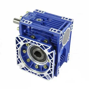
Common Problems and Troubleshooting for Worm Gearboxes
Worm gearboxes, like any mechanical component, can experience various issues over time. Here are some common problems that may arise and possible troubleshooting steps:
- Overheating: Overheating can occur due to factors such as inadequate lubrication, excessive loads, or high operating temperatures. Check lubrication levels, ensure proper ventilation, and reduce loads if necessary.
- Noise and Vibration: Excessive noise and vibration may result from misalignment, worn gears, or improper meshing. Check for misalignment, inspect gear teeth for wear, and ensure proper gear meshing.
- Leakage: Oil leakage can be caused by damaged seals or gaskets. Inspect seals and gaskets, and replace them if necessary.
- Reduced Efficiency: Efficiency loss can occur due to friction, wear, or misalignment. Regularly monitor gearbox performance, ensure proper lubrication, and address any wear or misalignment issues.
- Backlash: Excessive backlash can affect precision and accuracy. Adjust gear meshing and reduce backlash to improve performance.
- Seizure or Binding: Seizure or binding can result from inadequate lubrication, debris, or misalignment. Clean the gearbox, ensure proper lubrication, and address misalignment issues.
- Worn Gears: Worn gear teeth can lead to poor performance. Regularly inspect gears for signs of wear, and replace worn gears as needed.
- Seal Wear: Seals can wear over time, leading to leakage and contamination. Inspect seals regularly and replace them if necessary.
If you encounter any of these problems, it’s important to address them promptly to prevent further damage and maintain the performance of your worm gearbox. Regular maintenance, proper lubrication, and addressing issues early can help extend the lifespan and reliability of the gearbox.

Energy Efficiency of a Worm Gearbox: What to Expect
The energy efficiency of a worm gearbox is an important factor to consider when evaluating its performance. Here’s what you can expect in terms of energy efficiency:
- Typical Efficiency Range: Worm gearboxes are known for their compact size and high gear reduction capabilities, but they can exhibit lower energy efficiency compared to other types of gearboxes. The efficiency of a worm gearbox typically falls in the range of 50% to 90%, depending on various factors such as design, manufacturing quality, lubrication, and load conditions.
- Inherent Losses: Worm gearboxes inherently involve sliding contact between the worm and worm wheel. This sliding contact generates friction, leading to energy losses in the form of heat. The sliding action also contributes to lower efficiency when compared to gearboxes with rolling contact.
- Helical-Worm Design: Some manufacturers offer helical-worm gearbox designs that combine elements of helical and worm gearing. These designs aim to improve efficiency by incorporating helical gears in the reduction stage, which can lead to higher efficiency compared to traditional worm gearboxes.
- Lubrication: Proper lubrication plays a significant role in minimizing friction and improving energy efficiency. Using high-quality lubricants and ensuring the gearbox is adequately lubricated can help reduce losses due to friction.
- Application Considerations: While worm gearboxes might have lower energy efficiency compared to other types of gearboxes, they still offer advantages in terms of compactness, high torque transmission, and simplicity. Therefore, the decision to use a worm gearbox should consider the specific requirements of the application, including the trade-off between energy efficiency and other performance factors.
When selecting a worm gearbox, it’s essential to consider the trade-offs between energy efficiency, torque transmission, gearbox size, and the specific needs of the application. Regular maintenance, proper lubrication, and selecting a well-designed gearbox can contribute to achieving the best possible energy efficiency within the limitations of worm gearbox technology.

Preventing Backlash in a Worm Gearbox
Backlash in a worm gearbox can lead to reduced accuracy, positioning errors, and decreased overall efficiency. Here are steps to prevent or minimize backlash:
- High-Quality Components: Use high-quality worm gears and worm wheels with tight manufacturing tolerances. Precision components will help reduce backlash.
- Proper Meshing: Ensure the worm gear and worm wheel are properly aligned and meshed. Improper meshing can lead to increased backlash.
- Preload: Applying a small amount of preload to the worm gear can help reduce backlash. However, excessive preload can increase friction and wear.
- Anti-Backlash Mechanisms: Consider using anti-backlash mechanisms, such as spring-loaded systems or adjustable shims, to compensate for any inherent backlash.
- Lubrication: Proper lubrication can reduce friction and play a role in minimizing backlash. Use a lubricant that provides good film strength and reduces wear.
- Maintenance: Regularly inspect and maintain the gearbox to identify and address any changes in backlash over time.
It’s important to strike a balance between reducing backlash and maintaining smooth operation. Consulting with gearbox experts and following manufacturer guidelines will help you optimize your worm gearbox’s performance while minimizing backlash.


editor by CX 2023-09-13