Product Description
We specialize in forging parts for the axle, fifth wheel, hydraulic cylinder undercarriage of commercial vehicles, agricultural vehicles, construction machinery, railway.We can forging parts from 1kg-200kg.
Quality Manager System:
ISO 9001: 2008
ISO/TS 16949: 2008
| Material Specification | According to customer’s requirements. |
| Material incoming | Chemical Composition test Mechanical Performance test |
| Material cuting | Cutting machine |
| Heating | IF furnace |
| Forging equipments | 1000 ton friction press ,2500 ton friction press ,4000 ton friction press,8000 ton friction press |
| Hear treatment | Normalising , Soft annealing, Hardening and tempering,Heat treatment out of the forging heat ,Special treatments |
| Surface treatment | Shot blasting |
| Machining | CN Lathe , Milling , Drilling ,Grinding ,CNC |
| Cleaning | Remove flash, burr or flanging |
| Testing | Magnetic particle inspection , Hardness ,Dimension inspection |
| Package | Coated with anti-rust oil ,Put in the packages. |
Why choose us? :
1)A professional international sales team, which enable us to turn inquiries into final products and export them to numerous countries and regions without barriers;
2) A well managed quality control system to customize on clients requirements. We can design according to customers usage invironment.
3)Unparalleled after sales service.
FAQ
1. Are you a factory?
Yes, we are real factory supplier for over 10 years, own a super technical team to serve adjusting design for customers.
2. How about the products range do you produce?
We are specilized in producing a lot of types brake chamber for the brake system of truck and trailer. Product range as below:
3. Can you supply forging parts with adjustable design to adapt customers’ using requirment?
Sure, we have strong technology team, are CZPT to do adjustment design for customers according to users’ requirment and the using environment.
4. What advantages of your products and company?
1) adjusting design are available from us, to adapt the market and using environment better, and help customers gain more competitions in your market.
2)good price and quality
3) Strong production capacity and testing capabilities.
4) All of our forging parts passed the strict test before sale to customers.
| Processing Object: | Metal |
|---|---|
| Molding Style: | Forging |
| Application: | Auto Parts |
| Material: | Steel |
| Heat Treatment: | Normalizing |
| Surface Treatment: | Sand Blasting |
| Customization: |
Available
| Customized Request |
|---|
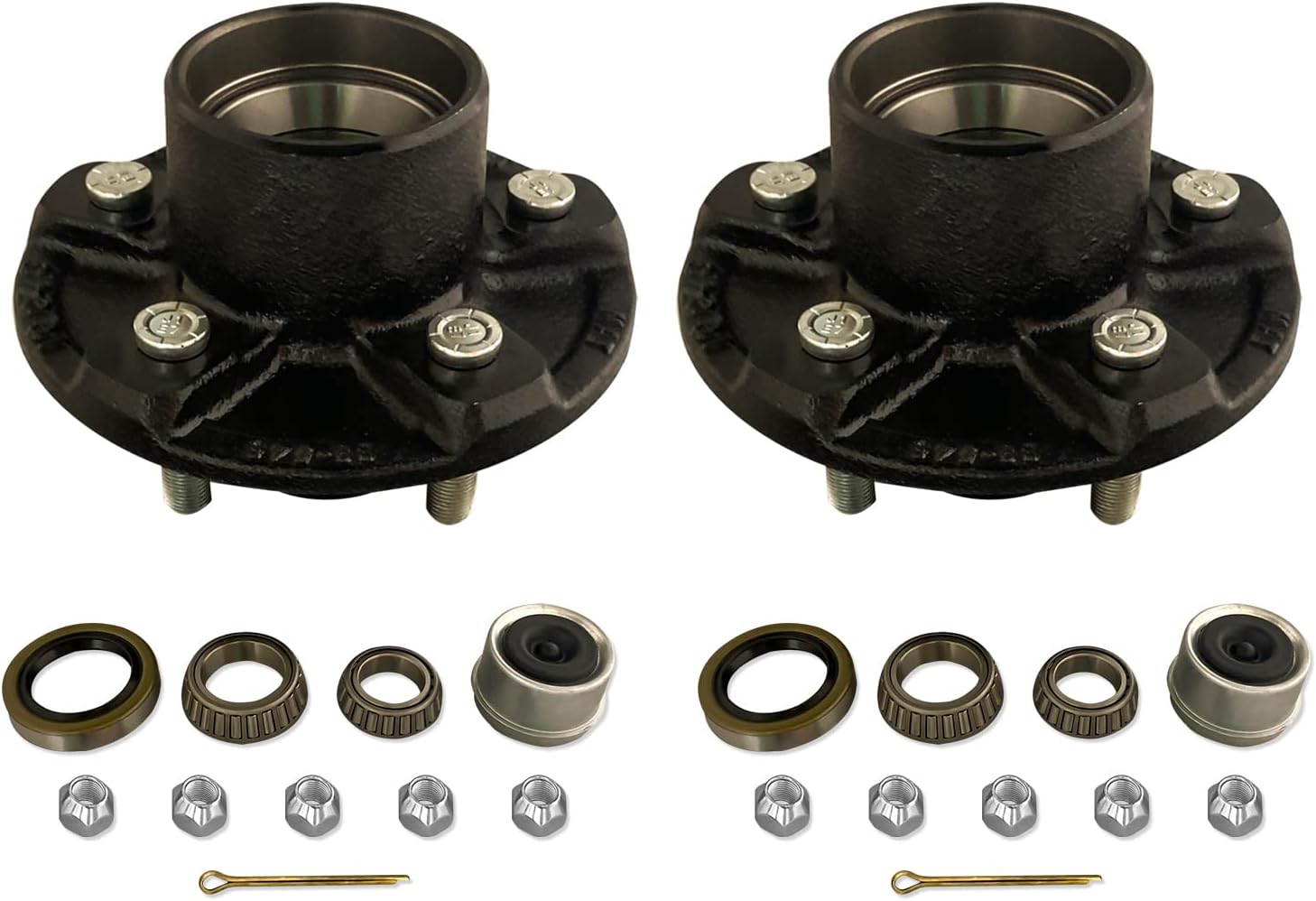
What is the primary function of an axle hub in a vehicle’s wheel assembly?
The primary function of an axle hub in a vehicle’s wheel assembly is to connect the wheel to the axle and provide a mounting point for the wheel bearings. Here’s a detailed explanation of the primary functions of an axle hub:
1. Wheel Mounting:
The axle hub serves as the component that connects the wheel to the vehicle’s axle. It is typically a cylindrical or disc-shaped structure located at the center of the wheel assembly. The hub contains bolt holes or studs that align with the corresponding holes or studs on the wheel, allowing for secure attachment and proper alignment of the wheel.
2. Bearing Support:
The axle hub provides a mounting point for the wheel bearings. Wheel bearings are crucial components that allow the wheel to rotate smoothly while supporting the weight of the vehicle. The hub contains a bearing race or races, which are machined surfaces that support the inner and outer wheel bearings. The bearings fit snugly into the hub and enable the wheel to rotate freely around the axle.
3. Load Transmission:
Another important function of the axle hub is to transmit the load from the wheel to the axle. As the vehicle moves, various forces act on the wheel, including the weight of the vehicle, acceleration and braking forces, and lateral forces during turns. The axle hub, along with the wheel bearings, helps distribute and transfer these forces from the wheel to the axle, allowing for smooth and controlled movement of the vehicle.
4. Hub Assembly Integration:
In many vehicles, the axle hub integrates with other components of the wheel assembly. For example, it may have provisions for attaching the brake rotor or drum, which are essential for the vehicle’s braking system. In vehicles with front-wheel drive or all-wheel drive, the axle hub may also incorporate features for connecting the CV (constant velocity) joint or driveshaft, allowing for power transmission to the wheels.
5. Wheel Alignment:
The axle hub plays a role in maintaining proper wheel alignment. The hub’s design and dimensions are critical in ensuring that the wheel is centered and aligned correctly with the vehicle’s suspension system. Proper wheel alignment is essential for optimal handling, tire wear, and overall vehicle performance.
In summary, the primary function of an axle hub in a vehicle’s wheel assembly is to connect the wheel to the axle and provide a mounting point for the wheel bearings. It facilitates the secure attachment of the wheel, supports the wheel bearings for smooth rotation, transmits loads from the wheel to the axle, integrates with other components of the wheel assembly, and contributes to proper wheel alignment. The axle hub is a critical component that enables safe and efficient operation of the vehicle’s wheels.
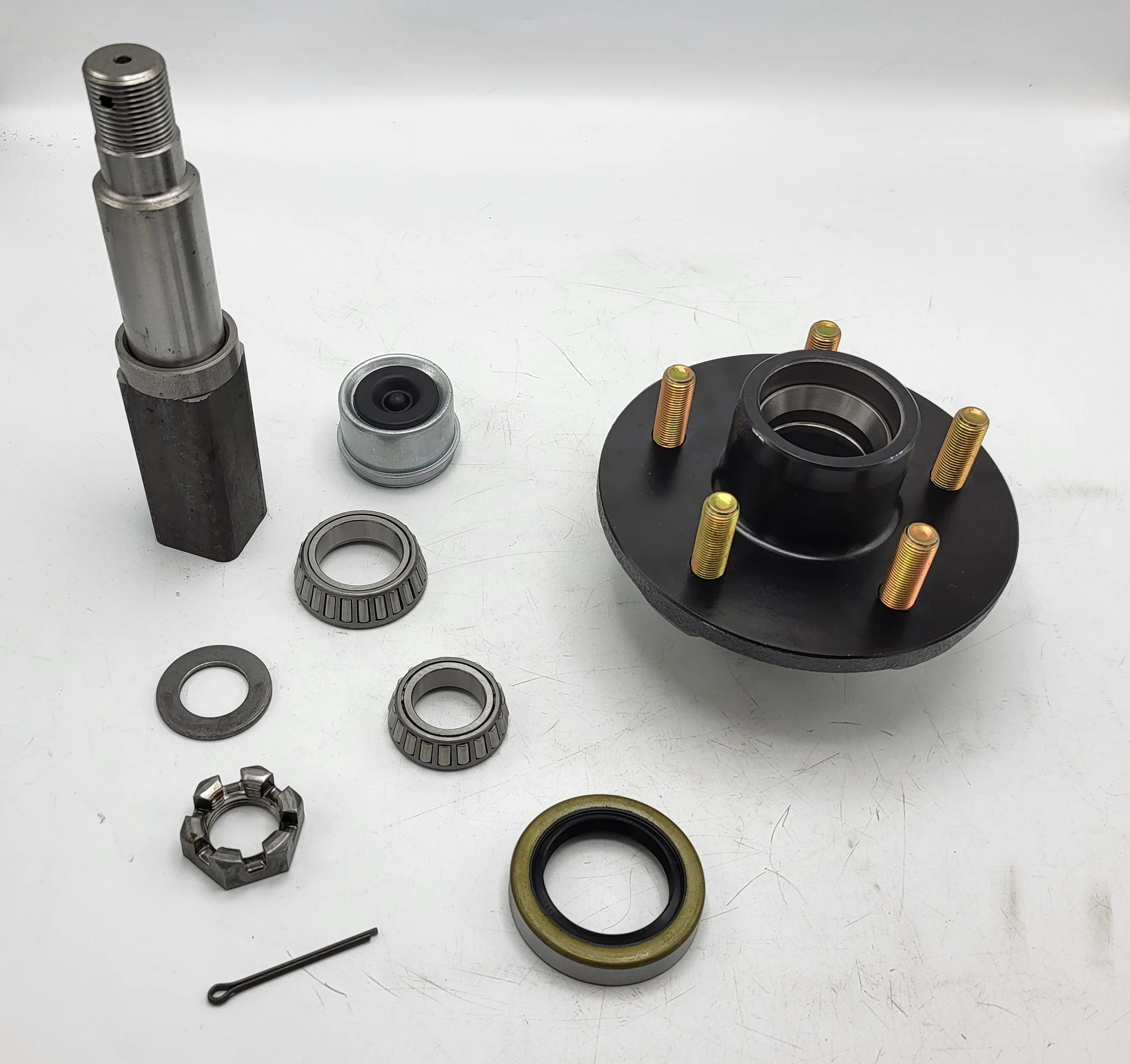
What role does the ABS sensor play in the context of an axle hub assembly?
The ABS (Anti-lock Braking System) sensor plays a crucial role in the context of an axle hub assembly. It is an integral component of the braking system and is responsible for monitoring the speed and rotational behavior of the wheels. Here’s a detailed explanation of the role of the ABS sensor in the context of an axle hub assembly:
- Wheel speed monitoring: The primary function of the ABS sensor is to monitor the rotational speed of the wheels. It does this by detecting the teeth or magnetic patterns on a tone ring or reluctor ring mounted on the axle hub or adjacent to the wheel hub. By continuously measuring the speed of each wheel, the ABS sensor provides crucial data to the vehicle’s ABS system.
- Anti-lock Braking System (ABS): The ABS system utilizes the data provided by the ABS sensors to determine if any wheel is about to lock up during braking. If a wheel is on the verge of locking up, the ABS system modulates the braking pressure to that wheel. This prevents the wheel from fully locking up, allowing the driver to maintain control of the vehicle and reducing the risk of skidding or loss of steering control.
- Traction control: In addition to aiding the ABS system, the ABS sensors also play a role in the vehicle’s traction control system. By continuously monitoring the rotational speed of the wheels, the ABS sensors assist in detecting any wheel slippage or loss of traction. When a wheel slips, the traction control system can adjust the engine power output or apply brake pressure to the specific wheel to regain traction and maintain stability.
- Stability control: Some modern vehicles incorporate stability control systems that rely on the ABS sensors to monitor the rotational behavior of the wheels. By comparing the speeds of individual wheels, the stability control system can detect and mitigate any potential loss of vehicle stability. This may involve applying brakes to specific wheels or adjusting engine power to help the driver maintain control in challenging driving conditions or during evasive maneuvers.
- Diagnostic capabilities: The ABS sensors also provide diagnostic capabilities for the vehicle’s onboard diagnostic system. In the event of a fault or malfunction within the ABS system, the ABS sensors can transmit error codes to the vehicle’s computer, which can then be retrieved using a diagnostic scanner. This aids in the identification and troubleshooting of ABS-related issues.
The ABS sensor is typically mounted near the axle hub, with its sensor tip in close proximity to the tone ring or reluctor ring. It generates electrical signals based on the detected rotational patterns, which are then transmitted to the vehicle’s ABS control module for processing and action.
In summary, the ABS sensor plays a vital role in the context of an axle hub assembly. It monitors the rotational speed of the wheels, providing essential data for the ABS system, traction control, and stability control. The ABS sensor helps prevent wheel lockup during braking, enhances traction in slippery conditions, aids in maintaining vehicle stability, and contributes to the diagnostic capabilities of the ABS system.
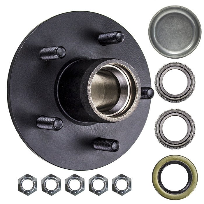
Are there any recalls or common issues associated with specific axle hub models?
Recalls and common issues can occur with specific axle hub models due to manufacturing defects, design flaws, or other factors. Here’s a detailed explanation:
It’s important to note that specific recalls and common issues can vary depending on the make, model, and year of the vehicle, as well as the specific axle hub manufacturer. Manufacturers and regulatory bodies such as the National Highway Traffic Safety Administration (NHTSA) monitor and address safety concerns related to axle hubs through recalls and investigations.
Recalls are typically initiated by the vehicle manufacturer or the axle hub manufacturer in response to identified safety defects or non-compliance with safety standards. Recalls aim to address the issues and rectify any potential safety risks associated with the axle hub models. They may involve inspections, repairs, or replacements of the affected components.
To determine if there are any recalls or common issues associated with specific axle hub models, it is recommended to check the following sources:
- Manufacturer’s Website: Visit the official website of the vehicle manufacturer or the axle hub manufacturer. They often provide information on recalls, technical service bulletins (TSBs), and common issues related to their products. Look for any relevant information specific to the axle hub models in question.
- NHTSA Website: The NHTSA maintains a comprehensive database of recalls and investigations related to vehicle components, including axle hubs. Their website allows users to search for recalls and investigations by specific make, model, and component. You can use their search tool to check if there are any recalls or investigations associated with the axle hub models of interest.
- Owner Forums and Online Communities: Online forums and communities dedicated to specific vehicle makes and models can be a valuable source of information. Owners often share their experiences, including common issues they have encountered with axle hub models. It’s important to consider multiple sources and exercise caution when relying on anecdotal information.
- Service Centers and Mechanics: Local service centers and mechanics who specialize in the specific vehicle make or have experience with the axle hub models in question may be aware of any recalls or common issues. They can provide insights based on their firsthand knowledge and experience.
By consulting these sources, you can gather information about any recalls or common issues associated with specific axle hub models. If any recalls or safety concerns are identified, it is recommended to contact the vehicle manufacturer or a certified dealership to inquire about the necessary actions, such as inspections or repairs, to address the issues.
In summary, recalls and common issues can occur with specific axle hub models. Checking the manufacturer’s website, the NHTSA website, owner forums, and consulting with service centers and mechanics can provide valuable information regarding any recalls or common issues associated with the axle hub models of interest. It’s important to stay informed and take appropriate actions to address any identified safety concerns.


editor by CX 2023-10-30
China Good quality 90 Degree Km Series Helical Hypoid Gear Reducer Price Mini Bevel Gearbox Worm Drive Shaft Gear Box car gearbox
Product Description
Product Description
90 degree KM Series Helical Hypoid Gear reducer price mini bevel gearbox worm drive shaft gear box
1.KM series Helical-hypoid Gearbox’s Characteristics
KM series helical-hypoid gearbox is a new-generation of product developed by Aokman. With a compromise of advanced technology both at home and abroad, its main features are as follows:
(1) Driven by hypoid gears, which has big ratios.
(2) Large output torque, high efficiency, energy saving and environmental protection.
(3) High-quality aluminum alloy housing, and light in weight and non-rusting.
(4) Smooth in running and low in noise, and can work long time in dreadful conditions.
(5) Good-looking in appearance, durable in service life and small in volume.
(6) Suitable for all round installation, wide application and easy use.
(7) The mounting dimension of KM series helical-hypoid gearbox are compatible with RV series worm gearbox.
(8) Modular and multi-structure can meet the demands of various conditions.
Detailed Photos
2. KM series Helical-hypoid Gearbox’s Main Materials
(1) Housing: die-cast aluminum alloy (frame size 27 to 57)
(2) Gear wheel: 20CrMnTiH1 carbonizing & quenching heat treatment make the hardness of gears surface be up to 56-62 HRC, and be retained carburization layers thickness between 0.3 and 0.5mm after precise grinding.
3. KM series Helical-hypoid Gearbox’s Surface Painting
Aluminum alloy housing:
(1) Shot blasting and special antiseptic treatment on the aluminum alloy surface.
(2) After phosphating, spray the RAL9571 silver white paint.4.Gearbox Parameters
Product Parameters
| Models | Stage | Nominal Ratio | Output Speed (n2)* | Max. Torque | Input Shaft Dia. | Output Hole Dia. | Output Shaft Dia. |
| KM050 | 3 Stage | 50~300 | 4.8~27 | 130N.m | Φ11 | Φ20, Φ24 | Φ25 |
| 2 Stage | 7.5~60 | 24~181 | 130N.m | Φ11 | |||
| KM063 | 3 Stage | 50~300 | 4.6~27 | 200N.m | Φ11 | Φ25, Φ28 | Φ25 |
| 2 Stage | 7.5~60 | 23~184 | 200N.m | Φ14 | |||
| KM075 | 3 Stage | 50~300 | 4.7~28 | 350N.m | Φ14 | Φ28, Φ30, Φ35 | Φ28 |
| 2 Stage | 7.5~60 | 24~187 | 350N.m | Φ16 | |||
| KM090 | 3 Stage | 50~300 | 4.7~28 | 500N.m | Φ14 | Φ35, Φ38 | Φ35 |
| 2 Stage | 7.5~60 | 24~187 | 500N.m | Φ19 | |||
| KM110 | 3 Stage | 50~300 | 4.7~27 | 750N.m | Φ19 | Φ40, Φ42 | Φ42 |
| 2 Stage | 7.5~60 | 24~187 | 750N.m | Φ24 |
Packaging & Shipping
Company Profile
Our Advantages
After Sales Service
| Pre-sale services | 1. Select equipment model. |
| 2.Design and manufacture products according to clients’ special requirement. | |
| 3.Train technical personal for clients | |
| Services during selling | 1.Pre-check and accept products ahead of delivery. |
| 2. Help clients to draft solving plans. | |
| After-sale services | 1.Assist clients to prepare for the first construction scheme. |
| 2. Train the first-line operators. | |
| 3.Take initiative to eliminate the trouble rapidly. | |
| 4. Provide technical exchanging. |
FAQ
1.Q:What kinds of gearbox can you produce for us?
A:Main products of our company: UDL series speed variator,RV series worm gear reducer, ATA series shaft mounted gearbox, X,B series gear reducer,
P series planetary gearbox and R, S, K, and F series helical-tooth reducer, more
than 1 hundred models and thousands of specifications
2.Q:Can you make as per custom drawing?
A: Yes, we offer customized service for customers.
3.Q:What is your terms of payment ?
A: 30% Advance payment by T/T after signing the contract.70% before delivery
4.Q:What is your MOQ?
A: 1 Set
If you have any demand for our products please feel free to contact me.
| Application: | Motor, Machinery |
|---|---|
| Function: | Speed Changing, Speed Reduction |
| Layout: | Orthogonal |
| Hardness: | Hardened Tooth Surface |
| Installation: | Industry |
| Step: | Double or Three-Step |
| Customization: |
Available
| Customized Request |
|---|
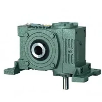
Can a Worm Gearbox Be Used in Heavy-Duty Machinery?
Yes, a worm gearbox can be used in heavy-duty machinery and is often chosen for such applications due to its inherent characteristics and advantages:
- High Torque Transmission: Worm gearboxes are known for their ability to transmit high torque loads, making them suitable for heavy-duty machinery that requires significant power transmission.
- Load Distribution: The design of worm gears provides robust load distribution and excellent contact between the worm and worm wheel teeth. This enhances their load-carrying capacity, making them capable of handling heavy loads without premature wear or failure.
- Compact Design: Worm gearboxes are compact and offer high reduction ratios in a single stage. This allows for the reduction of high input speeds to lower output speeds, often required in heavy-duty machinery.
- Overload Protection: Worm gears have a natural self-locking feature, which means the gear cannot be easily back-driven by external forces. This feature provides inherent overload protection, preventing damage to the gearbox and machinery in cases of sudden load spikes.
- Smooth Operation: Worm gearboxes offer smooth and steady operation, which is crucial for heavy-duty machinery where precision and controlled movement are essential.
However, when considering the use of a worm gearbox in heavy-duty applications, it’s important to ensure proper engineering and sizing. The design should account for factors such as load, speed, duty cycle, lubrication, and temperature to ensure optimal performance and longevity.
Overall, worm gearboxes are well-suited for heavy-duty machinery across various industries, including mining, construction, manufacturing, and more.
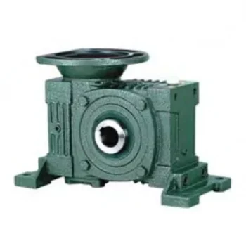
Materials Used for Worm Gears
Worm gears are manufactured using a variety of materials to meet different application requirements. Some commonly used materials for worm gears include:
- Steel: Steel is a popular choice for worm gears due to its strength, durability, and wear resistance. It can handle heavy loads and is often used in industrial applications.
- Bronze: Bronze offers good lubricity and is commonly used for the worm gear (worm) component. It provides effective wear resistance and works well in applications where quiet operation is essential.
- Cast Iron: Cast iron is known for its high strength and durability. It’s often used for worm gears in applications where shock loads or heavy-duty conditions are expected.
- Aluminum: Aluminum worm gears are lightweight and corrosion-resistant, making them suitable for applications where weight reduction is important.
- Plastic: Some worm gears are made from plastic materials such as nylon or acetal. These materials are often chosen for their self-lubricating properties and quiet operation.
- Composite Materials: Composite materials can offer a combination of properties, such as lightweight construction and corrosion resistance. They can be suitable for specific applications.
The choice of material depends on factors such as the application’s load, speed, operating environment, and required performance characteristics. It’s important to consider these factors when selecting the appropriate material for worm gears to ensure optimal performance and longevity.
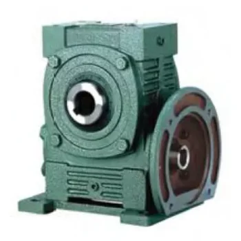
How to Select the Right Worm Gearbox for Your Application
Selecting the right worm gearbox for your application involves careful consideration of various factors:
- Load Requirements: Determine the torque and load requirements of your application to ensure the selected gearbox can handle the load without compromising performance.
- Speed Reduction: Calculate the required gear reduction ratio to achieve the desired output speed. Worm gearboxes are known for high reduction ratios.
- Efficiency: Consider the gearbox’s efficiency, as worm gearboxes typically have lower efficiency due to the sliding action. Evaluate whether the efficiency meets your application’s needs.
- Space Constraints: Assess the available space for the gearbox. Worm gearboxes have a compact design, making them suitable for applications with limited space.
- Mounting Options: Determine the mounting orientation and configuration that best suits your application.
- Operating Environment: Consider factors such as temperature, humidity, and exposure to contaminants. Choose a gearbox with appropriate seals and materials to withstand the environment.
- Backlash: Evaluate the acceptable level of backlash in your application. Worm gearboxes may exhibit more backlash compared to other gear types.
- Self-Locking: If self-locking capability is required, confirm that the selected gearbox can prevent reverse motion without the need for external braking mechanisms.
- Maintenance: Consider the maintenance requirements of the gearbox. Some worm gearboxes require periodic lubrication and maintenance to ensure proper functioning.
- Cost: Balance the features and performance of the gearbox with the overall cost to ensure it aligns with your budget.
Consult with gearbox manufacturers or experts to get recommendations tailored to your specific application. Testing and simulations can also help validate the suitability of a particular gearbox for your needs.


editor by CX 2023-09-13
China best Manufacturer High Quality Performance Hydraulic Brake Pump Parts Brake Wheel Cylinder 9010515 with Hot selling
Product Description
Products Description
FRJX,manufacturer of professional brake and suspension parts from China.All of our products are manufactured and 100% tested to meet standards of SGS.
we offer comes in various OE numbers and capabilities to meet your needs with high performance and competitive price.
| Catagory | Brake Wheel Cylinder |
| Brand | OEM /Customized/FRJX |
| Application | Auto Brake Systems |
| OEM No. | 9571515 |
| Car Model | For Chevrolet |
| Material | Iron/Aluminum |
| Sample | Available |
| MOQ | 50-100PCS |
| Warranty | 30,000 kms/1 year |
| Quality | 100% Tested 1 by 1 before shipment |
| Packing | Plastic Bag+Color Box+Carton+Customize |
| Lead Time | 7-15 days for stock orders, 25-40 days for large quantities. |
FRJX,from high quality material to advanced processing and test equipment,all our brake and clutch parts are manufactured and 100% tested to meet standards ISO9001 and ISO/TS 16949 and SGS.
Company Introduction
In 2008, the HangZhou Fanrong Machinery Co.,Ltd was created in the city of HangZhou ,ZheJiang ,China,our vision is to produce a high quality of Brake and Suspension parts competitive prices to satisfy the needs of the auto market and gain the trust of our customers.
The supervision of our production processes is carried out by highly qualified engineers and specialists who have state-of-the-art instruments, ensuring that the final result is excellent quality products with high levels of safety, durability and performance. The adequate selection of the best quality raw materials , strict controls in the production process, make us recognized with the ISO9001 and ISO/TS 16949 certifications. Additionally, we have outstanding results in tests carried out by our customers.
We respond to the reliability and safety needs of the auto parts sector by offering the best auto parts for vehicles.Due to our high performance and competitive price,our Brake and Suspension parts production is our best-selling.
We believe our qualified products with reasonable price could save you a lot! welcome your inquiry!
Precessing Equipment
Assembly & Testing
Package & Delivery
| After-sales Service: | 1 Year |
|---|---|
| Warranty: | 1 Year |
| Type: | Brake System |
| Material: | Iron or Aluminum, Iron |
| Position: | Front, Rear |
| Certification: | ISO/TS16949, ISO9001, ISO9002 |
| Samples: |
US$ 5/Piece
1 Piece(Min.Order) | |
|---|
| Customization: |
Available
|
|
|---|
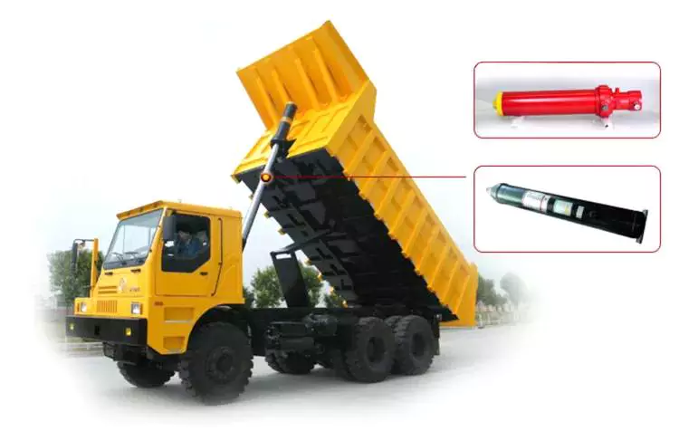
Can hydraulic cylinders be adapted for specialized applications like material handling?
Yes, hydraulic cylinders can be effectively adapted for specialized applications such as material handling. The versatility, power, and precise control offered by hydraulic cylinders make them well-suited for a wide range of material handling tasks. Hydraulic systems, including cylinders, are commonly used in industrial settings to lift, position, push, pull, and manipulate various types of materials. Here’s a detailed explanation of how hydraulic cylinders can be adapted for specialized material handling applications:
1. Lifting and Lowering:
– Hydraulic cylinders are commonly used for lifting and lowering heavy loads in material handling applications. By utilizing the force generated by hydraulic pressure, cylinders can provide the necessary power to lift and hold loads at different elevations. The precise control offered by hydraulic systems allows for accurate positioning of materials, ensuring efficient and safe lifting operations.
2. Pushing and Pulling:
– Hydraulic cylinders are capable of generating substantial pushing and pulling forces, making them ideal for applications that involve moving or manipulating materials. They can be used to push or pull heavy objects, control the movement of conveyors or rollers, or engage mechanisms for material transfer. The ability to exert high forces with precise control enables hydraulic cylinders to efficiently handle a variety of material handling tasks.
3. Tilting and Rotating:
– Hydraulic cylinders can be adapted to provide tilting and rotating functions in material handling equipment. By integrating cylinders into the design, equipment such as forklifts, cranes, or material handling arms can tilt or rotate to facilitate material placement or maneuvering. Hydraulic cylinders offer the required force and control to achieve smooth and controlled tilting or rotating motions, enhancing operational efficiency in material handling processes.
4. Gripping and Clamping:
– Hydraulic cylinders can be utilized to provide gripping and clamping functions for secure material handling. By incorporating specialized gripping or clamping mechanisms with hydraulic actuation, materials of various shapes and sizes can be securely held or clamped during transportation or processing. Hydraulic cylinders enable precise and adjustable gripping or clamping forces, ensuring the safe and reliable handling of materials.
5. Material Compaction and Forming:
– Hydraulic cylinders can be adapted for material compaction and forming applications. For example, in the production of bricks, hydraulic cylinders are used to apply high pressure and force to compact the raw materials into desired shapes. Similarly, in metal forming processes, hydraulic cylinders are employed to exert force on metal sheets or components, enabling precise shaping and forming operations.
6. Conveyor and Sorting Systems:
– Hydraulic cylinders can be integrated into conveyor and sorting systems to facilitate material movement and sorting. By incorporating hydraulic actuators, conveyor belts or sorting mechanisms can be efficiently controlled for optimal material flow and distribution. Hydraulic cylinders provide the necessary force and control to handle varying load capacities and adjust the speed and position of material transfer, improving the overall efficiency of handling and sorting operations.
7. Customized Designs:
– Hydraulic cylinders can be customized and adapted to meet specific requirements of specialized material handling applications. Engineers can design cylinders with unique dimensions, stroke lengths, mounting options, and sealing arrangements to fit into equipment or systems with specific space limitations or operating conditions. Customized hydraulic cylinders ensure optimal performance and compatibility for specialized material handling tasks.
In summary, hydraulic cylinders can be effectively adapted for specialized material handling applications, offering the necessary force, control, and versatility required in various material handling tasks. Whether it involves lifting and lowering, pushing and pulling, tilting and rotating, gripping and clamping, material compaction and forming, or integration into conveyor and sorting systems, hydraulic cylinders provide reliable and efficient solutions. Their adaptability, precise control, and ability to handle heavy loads make hydraulic cylinders a valuable component in optimizing material handling processes across different industries.
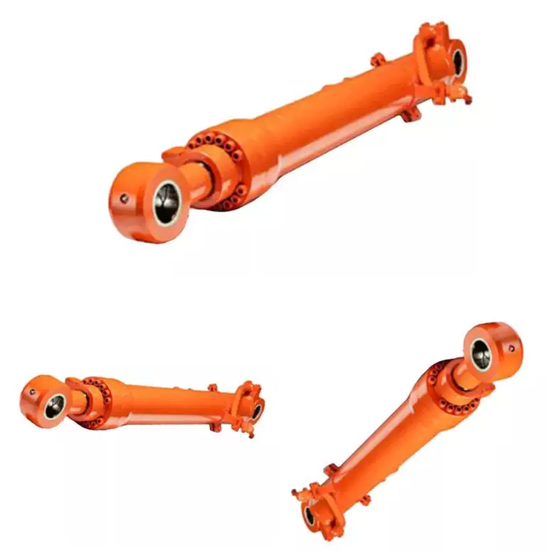
Handling the Challenges of Minimizing Fluid Leaks and Contamination in Hydraulic Cylinders
Hydraulic cylinders face challenges when it comes to minimizing fluid leaks and contamination, as these issues can impact the performance, reliability, and lifespan of the system. However, there are several measures and design considerations that help address these challenges effectively. Let’s explore how hydraulic cylinders handle the challenges of minimizing fluid leaks and contamination:
- Sealing Systems: Hydraulic cylinders employ advanced sealing systems to prevent fluid leaks. These systems typically include various types of seals, such as piston seals, rod seals, and wiper seals. The seals are designed to create a tight and reliable barrier between the moving components of the cylinder and the external environment, minimizing the risk of fluid leakage.
- Seal Material Selection: The choice of seal materials is crucial in minimizing fluid leaks and contamination. Hydraulic cylinder manufacturers carefully select seal materials that are compatible with the hydraulic fluid used and resistant to wear, abrasion, and chemical degradation. This ensures the longevity and effectiveness of the seals, reducing the likelihood of leaks or premature seal failure.
- Proper Installation and Maintenance: Ensuring proper installation and regular maintenance of hydraulic cylinders is essential for minimizing fluid leaks and contamination. During installation, attention should be given to proper alignment, torqueing of bolts, and adherence to recommended procedures. Regular maintenance includes inspecting seals, replacing worn-out components, and addressing any signs of leakage promptly. Proper maintenance practices help identify and rectify issues before they escalate and cause significant problems.
- Contamination Control: Hydraulic cylinders incorporate measures to control contamination and maintain fluid cleanliness. This includes the use of filtration systems, such as in-line filters, to remove particles and contaminants from the hydraulic fluid. Additionally, hydraulic reservoirs often have breathers and desiccant filters to prevent moisture and airborne contaminants from entering the system. By controlling contamination, hydraulic cylinders minimize the risk of damage to internal components and maintain optimal system performance.
- Environmental Protection: Hydraulic cylinders may be equipped with protective features to safeguard against external contaminants. For example, bellows or protective boots can be installed to shield the rod and seals from debris, dirt, or moisture present in the operating environment. These protective measures help extend the life of the seals and enhance the overall reliability of the hydraulic cylinder.
In summary, hydraulic cylinders employ sealing systems, appropriate seal materials, proper installation and maintenance practices, contamination control measures, and environmental protection features to handle the challenges of minimizing fluid leaks and contamination. By implementing these measures, manufacturers can ensure reliable and long-lasting hydraulic cylinder performance, minimize the risk of fluid leakage, and maintain the cleanliness of the hydraulic system.
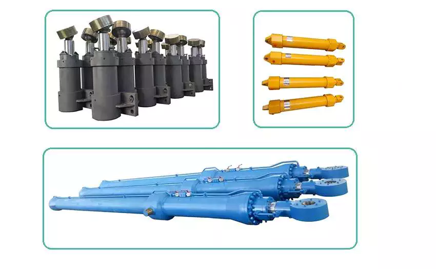
Can hydraulic cylinders be adapted for use in both industrial and mobile equipment?
Yes, hydraulic cylinders can be adapted for use in both industrial and mobile equipment. The versatility and adaptability of hydraulic systems make them suitable for a wide range of applications across various industries. Here’s a detailed explanation:
1. Industrial Equipment:
– Hydraulic cylinders are extensively used in industrial equipment such as manufacturing machinery, construction equipment, material handling systems, and heavy-duty machinery. They provide the necessary force and controlled movement for tasks such as lifting, pushing, pulling, and positioning heavy loads. Industrial hydraulic cylinders are typically designed for robustness, durability, and high load-bearing capacities to withstand the demanding environments and heavy-duty applications encountered in industries.
2. Mobile Equipment:
– Hydraulic cylinders are also widely adopted in mobile equipment, including agricultural machinery, mining equipment, forestry machinery, and transportation vehicles. These cylinders enable various functions such as tilting, lifting, steering, and stabilizing. Mobile hydraulic cylinders are designed to be compact, lightweight, and efficient to meet the specific requirements of mobile applications. They are often integrated into hydraulic systems that power multiple functions in a single machine.
3. Adaptability:
– One of the key advantages of hydraulic cylinders is their adaptability. They can be customized and configured to suit different operating conditions, equipment sizes, load capacities, and speed requirements. Hydraulic cylinder manufacturers offer a wide range of sizes, stroke lengths, mounting options, and rod configurations to accommodate diverse applications. This adaptability allows hydraulic cylinders to be utilized in both industrial and mobile equipment, serving various purposes across different sectors.
4. Mounting Options:
– Hydraulic cylinders can be adapted to different mounting arrangements to suit the specific requirements of industrial and mobile equipment. They can be mounted in various orientations, including vertical, horizontal, or at an angle. Different mounting options, such as flange mounts, trunnion mounts, and clevis mounts, provide flexibility in integrating hydraulic cylinders into different equipment designs.
5. Integration with Hydraulic Systems:
– Hydraulic cylinders are often part of a larger hydraulic system that includes components such as pumps, valves, hoses, and reservoirs. These systems can be tailored to meet the specific needs of both industrial and mobile equipment. The hydraulic system’s design and configuration can be adapted to provide the necessary flow rates, pressures, and control mechanisms required for optimal performance in the intended application.
6. Control and Automation:
– Hydraulic cylinders in both industrial and mobile equipment can be integrated with control systems and automation technologies. This allows for precise and automated control of the cylinder’s movement and function. Proportional control valves, sensors, and electronic controls can be incorporated to achieve accurate positioning, speed control, and synchronization of multiple hydraulic cylinders, enhancing overall equipment performance and productivity.
7. Safety Considerations:
– Hydraulic cylinders for both industrial and mobile equipment are designed with safety in mind. They often feature built-in safety mechanisms such as overload protection, pressure relief valves, and emergency stop systems to prevent accidents and equipment damage. Safety standards and regulations specific to each industry are taken into account during the design and adaptation of hydraulic cylinders for different applications.
Overall, hydraulic cylinders offer the adaptability and performance required for use in both industrial and mobile equipment. Their versatility, customizable features, mounting options, integration capabilities, and safety considerations make them suitable for a wide range of applications across diverse industries. Whether it’s heavy-duty industrial machinery or mobile equipment operating in challenging environments, hydraulic cylinders can be adapted to meet the specific needs and requirements of various equipment types.


editor by CX 2023-09-13
China high quality Hob 63X100 Hob -63-150 Hob -63X250 Hydraulics Cylinders, Air Hydraulic Cylinder wholesaler
Product Description
HOB 63×100 HOB -63-150 HOB -63×250 hydraulics cylinders , air hydraulic cylinder
HOB series hydro-cylinder is heavy type hydraulic cylinder, give the derive cylinder of double rod type and stroke adjustable type, varies of installments are optional to meet different requirement, also can be customized. Widely used in hydro-power engineering projects, metallurgical industry, construction industry, aviation and cosmonautical industry, cranes, textile & chemical industry, plastic injection mounding machines, elevators, ship-lifts, offshore well-drilling platforms, etc.
Model:
| HOB 40×50 | HOB 50×50 | HOB 63×50 | HOB 80×50 | HOB 100×50 | HOB 125×50 |
| HOB 40×100 | HOB 50×100 | HOB 63×100 | HOB 80×100 | HOB 100×100 | HOB 125×100 |
| HOB 40×150 | HOB 50×150 | HOB 63×150 | HOB 80×150 | HOB 100×150 | HOB 125×150 |
| HOB 40×200 | HOB 50×200 | HOB 63×200 | HOB 80×200 | HOB 100×200 | HOB 125×200 |
| HOB 40×250 | HOB 50×250 | HOB 63×250 | HOB 80×250 | HOB 100×250 | HOB 125×250 |
| HOB 40×300 | HOB 50×300 | HOB 63×300 | HOB 80×300 | HOB 100×300 | HOB 125×300 |
| HOB 40×350 | HOB 50×350 | HOB 63×350 | HOB 80×350 | HOB 100×350 | HOB 125×350 |
| HOB 40×400 | HOB 50×400 | HOB 63×400 | HOB 80×400 | HOB 100×400 | HOB 125×400 |
| HOB 40×450 | HOB 50×450 | HOB 63×450 | HOB 80×450 | HOB 100×450 | HOB 125×450 |
| HOB 40×500 | HOB 50×500 | HOB 63×500 | HOB 80×500 | HOB 100×500 | HOB 125×500 |
| HOB 40×600 | HOB 50×600 | HOB 63×600 | HOB 80×600 | HOB 100×600 | HOB 125×600 |
| HOB 40×700 | HOB 50×700 | HOB 63×700 | HOB 80×700 | HOB 100×700 | HOB 125×700 |
| HOB 40×800 | HOB 50×800 | HOB 63×800 | HOB 80×800 | HOB 100×800 | HOB 125×800 |
| HOB 40×900 | HOB 50×900 | HOB 63×900 | HOB 80×900 | HOB 100×900 | HOB 125×900 |
| HOB 40×1000 | HOB 50×1000 | HOB 63×1000 | HOB 80×1000 | HOB 100×1000 | HOB 125×1000 |
| HOB 150×50 | HOB 160×50 | HOB180x50 | HOB 200×50 | HOB 250×50 |
| HOB 150×100 | HOB 160×100 | HOB 180×100 | HOB 200×100 | HOB 250×100 |
| HOB 150×150 | HOB 160×150 | HOB 180×150 | HOB 200×150 | HOB 250×150 |
| HOB 150×200 | HOB 160×200 | HOB180x200 | HOB200x200 | HOB 250×200 |
| HOB 150×250 | HOB 160×250 | HOB 180×250 | HOB 200×250 | HOB 250×250 |
| HOB 150×300 | HOB 160×300 | HOB 180×300 | HOB 200×300 | HOB 250×300 |
| HOB 150×350 | HOB 160×350 | HOB 180×350 | HOB 200×350 | HOB 250×350 |
| HOB150x400 | HOB 160×400 | HOB180x400 | HOB 200×400 | HOB 250×400 |
| HOB 150×450 | HOB 160×450 | HOB 180×450 | HOB 200×450 | HOB 250×450 |
| HOB 150×500 | HOB 160×500 | HOB 180×500 | HOB 200×500 | HOB 250×500 |
| HOB 150×600 | HOB 160×600 | HOB 180×600 | HOB 200×600 | HOB 250×600 |
| HOB 150×700 | HOB 160×700 | HOB 180×700 | HOB 200×700 | HOB 250×700 |
| HOB 150×800 | HOB 160×800 | HOB 180×800 | HOB 200×800 | HOB 250×800 |
| HOB 150×900 | HOB 160×900 | HOB 180×900 | HOB 200×900 | HOB 250×900 |
| HOB 150×1000 | HOB 160×1000 | HOB 180×1000 | HOB 200×1000 | HOB 250×1000 |
Product details:
| Certification: | GS, CE, ISO9001 |
|---|---|
| Pressure: | Medium Pressure |
| Work Temperature: | High Temperature |
| Acting Way: | Double Acting |
| Working Method: | Straight Trip |
| Adjusted Form: | Regulated Type |
| Samples: |
US$ 30/Piece
1 Piece(Min.Order) | |
|---|
| Customization: |
Available
|
|
|---|

How do hydraulic cylinders compare to other methods of force generation like electric motors?
Hydraulic cylinders and electric motors are two different methods of force generation with distinct characteristics and applications. While both hydraulic cylinders and electric motors can generate force, they differ in terms of their working principles, performance attributes, and suitability for specific applications. Here’s a detailed comparison of hydraulic cylinders and electric motors:
1. Working Principle:
– Hydraulic Cylinders: Hydraulic cylinders generate force through the conversion of fluid pressure into linear motion. They consist of a cylinder barrel, piston, piston rod, and hydraulic fluid. When pressurized hydraulic fluid enters the cylinder, it pushes against the piston, causing the piston rod to extend or retract, thereby generating linear force.
– Electric Motors: Electric motors generate force through the conversion of electrical energy into rotational motion. They consist of a stator, rotor, and electromagnetic field. When an electrical current is applied to the motor’s windings, it creates a magnetic field that interacts with the rotor, causing it to rotate and generate torque.
2. Force and Power:
– Hydraulic Cylinders: Hydraulic cylinders are known for their high force capabilities. They can generate substantial linear forces, making them suitable for heavy-duty applications that require lifting, pushing, or pulling large loads. Hydraulic systems can provide high force output even at low speeds, allowing for precise control over force application. However, hydraulic systems typically operate at lower speeds compared to electric motors.
– Electric Motors: Electric motors excel in providing high rotational speeds and are commonly used for applications that require rapid motion. While electric motors can generate significant torque, they tend to have lower force output compared to hydraulic cylinders. Electric motors are suitable for applications that involve continuous rotary motion, such as driving conveyor belts, rotating machinery, or powering vehicles.
3. Control and Precision:
– Hydraulic Cylinders: Hydraulic systems offer excellent control over force, speed, and positioning. By regulating the flow of hydraulic fluid, the force and speed of hydraulic cylinders can be precisely controlled. Hydraulic systems can provide gradual acceleration and deceleration, allowing for smooth and precise movements. This level of control makes hydraulic cylinders well-suited for applications that require precise positioning, such as in industrial automation or construction equipment.
– Electric Motors: Electric motors also offer precise control over speed and positioning. Through motor control techniques such as varying voltage, frequency, or pulse width modulation (PWM), the rotational speed and position of electric motors can be accurately controlled. Electric motors are commonly used in applications that require precise speed control, such as robotics, CNC machines, or servo systems.
4. Efficiency and Energy Consumption:
– Hydraulic Cylinders: Hydraulic systems can be highly efficient, especially when properly sized and designed. However, hydraulic systems typically have higher energy losses due to factors such as fluid leakage, friction, and heat generation. The overall efficiency of a hydraulic system depends on the design, component selection, and maintenance practices. Hydraulic systems require a hydraulic power unit to pressurize the hydraulic fluid, which consumes additional energy.
– Electric Motors: Electric motors can have high efficiency, especially when operated at their optimal operating conditions. Electric motors have lower energy losses compared to hydraulic systems, primarily due to the absence of fluid leakage and lower friction losses. The overall efficiency of an electric motor depends on factors such as motor design, load conditions, and control techniques. Electric motors require an electrical power source, and their energy consumption depends on the motor’s power rating and the duration of operation.
5. Environmental Considerations:
– Hydraulic Cylinders: Hydraulic systems typically use hydraulic fluids that can pose environmental concerns if they leak or are not properly disposed of. The choice of hydraulic fluid can impact factors such as biodegradability, toxicity, and potential environmental hazards. Proper maintenance and leak prevention practices are essential to minimize the environmental impact of hydraulic systems.
– Electric Motors: Electric motors are generally considered more environmentally friendly since they do not require hydraulic fluids. However, the environmental impact of electric motors depends on the source of electricity used to power them. When powered by renewable energy sources, such as solar or wind, electric motors can offer a greener solution compared to hydraulic systems.
6. Application Suitability:
– Hydraulic Cylinders: Hydraulic cylinders are commonly used in applications that require high force output, precise control, and durability. They are widely employed in industries such as construction, manufacturing, mining, and aerospace. Hydraulic systems are well-suited for heavy-duty applications, such as lifting heavy objects, operating heavy machinery, or controlling large-scale movements.
– Electric Motors: Electric motors are widely used in various industries and applications that require rotational motion, speed control, and precise positioning. They are commonly found in appliances, transportation, robotics, HVAC systems, and automation. Electric motorsare suitable for applications that involve continuous rotary motion, such as driving conveyor belts, rotating machinery, or powering vehicles.In summary, hydraulic cylinders and electric motors have different working principles, force capabilities, control characteristics, efficiency levels, and application suitability. Hydraulic cylinders excel in providing high force output, precise control, and durability, making them ideal for heavy-duty applications. Electric motors, on the other hand, offer high rotational speeds, precise speed control, and are commonly used for applications that involve continuous rotary motion. The choice between hydraulic cylinders and electric motors depends on the specific requirements of the application, including the type of motion, force output, control precision, and environmental considerations.
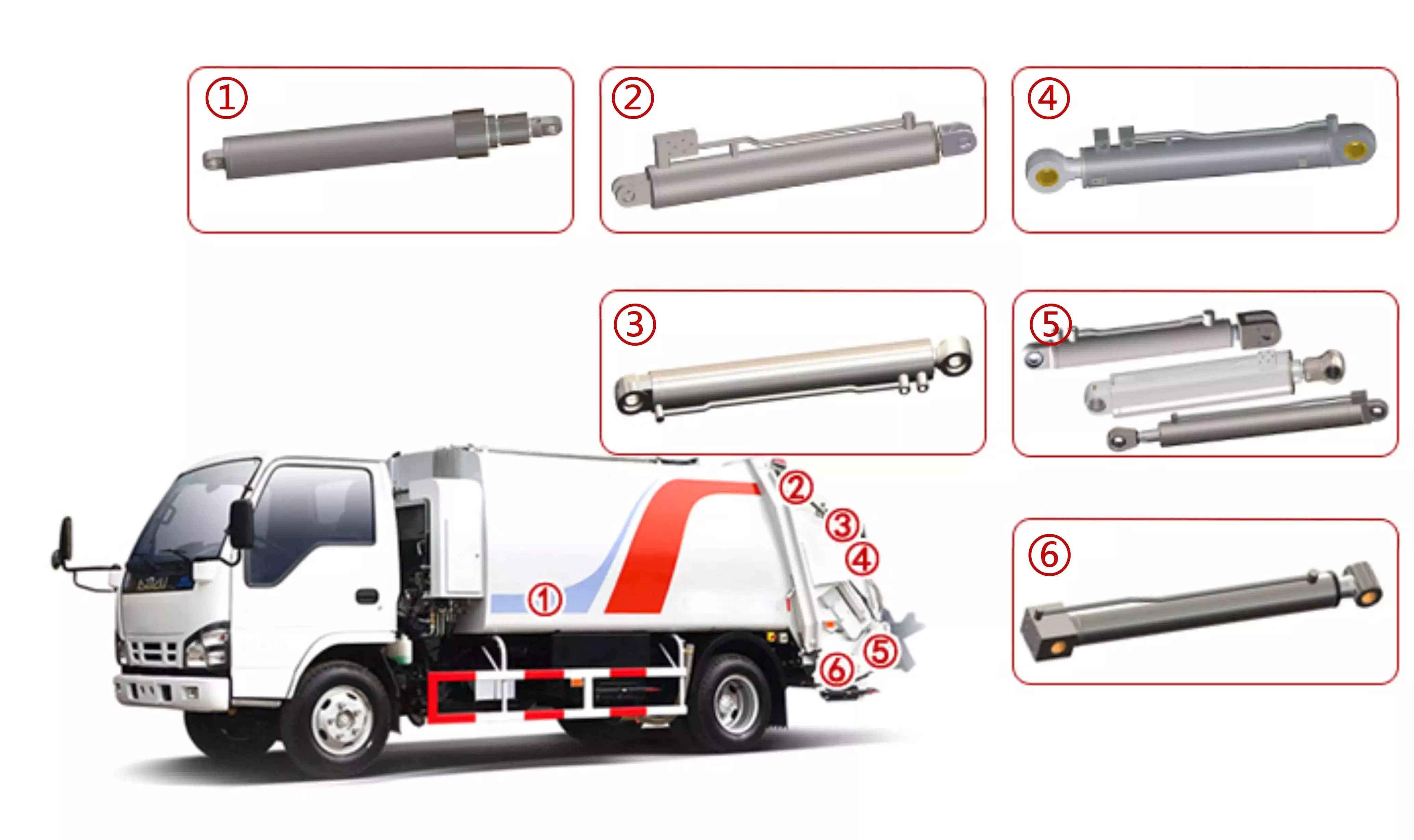
How do hydraulic cylinders contribute to the efficiency of agricultural tasks like plowing?
Hydraulic cylinders play a crucial role in improving the efficiency of agricultural tasks, including plowing. These cylinders provide several benefits that enhance the performance and productivity of agricultural machinery. Let’s explore how hydraulic cylinders contribute to the efficiency of plowing and other agricultural tasks:
- Powerful Force Generation: Hydraulic cylinders are capable of generating high forces, which is essential for tasks like plowing. The hydraulic system supplies pressurized fluid to the cylinders, converting hydraulic energy into mechanical force. This force is then utilized to drive plow blades through the soil, overcoming resistance and facilitating efficient soil penetration. The power generated by hydraulic cylinders ensures effective plowing, even in tough or compacted soil conditions.
- Adjustable Working Depth: Hydraulic cylinders allow for easy and precise adjustment of the plow’s working depth. By controlling the extension or retraction of the hydraulic cylinder, farmers can adjust the depth of the plow blades according to soil conditions, crop requirements, or their specific preferences. This adjustability enhances efficiency by ensuring optimal soil tillage and minimizing unnecessary energy expenditure. Farmers can adapt the plowing depth to different field areas, optimizing the use of resources and promoting uniform crop growth.
- Responsive Control: Hydraulic systems offer highly responsive control, enabling farmers to make quick adjustments during plowing operations. Hydraulic cylinders respond rapidly to changes in hydraulic pressure and valve settings, allowing for immediate modifications in the plow’s position, depth, or angle. This responsiveness enhances efficiency by facilitating on-the-go adjustments based on soil variations, obstacles, or changing field conditions. Farmers can maintain precise control over the plow’s performance, ensuring effective soil tillage and minimizing the risk of crop damage.
- Implement Versatility: Hydraulic cylinders enable the attachment of various implements to agricultural machinery, expanding their functionality and versatility. In the context of plowing, hydraulic cylinders allow for the attachment and detachment of plow blades or other tillage implements. This versatility enables farmers to adapt their equipment to different soil types, field sizes, or specific plowing requirements. By using hydraulic cylinders, farmers can easily switch between different implements, optimizing their equipment for specific tasks and maximizing efficiency.
- Efficient Time Management: Hydraulic cylinders contribute to time efficiency in agricultural tasks like plowing. With hydraulic systems, farmers can operate plows at higher speeds while maintaining control and precision. The responsive nature of hydraulic cylinders allows for efficient turning, maneuvering, and repositioning of plows, minimizing downtime and optimizing field coverage. This time efficiency translates into increased productivity and reduced overall operational costs. Farmers can accomplish plowing tasks more quickly, allowing them to cover larger field areas in less time.
In summary, hydraulic cylinders significantly contribute to the efficiency of agricultural tasks like plowing. Through powerful force generation, adjustable working depth, responsive control, implement versatility, and efficient time management, hydraulic systems equipped with cylinders enhance the performance and productivity of agricultural machinery. These contributions allow farmers to accomplish plowing tasks more effectively, optimize field operations, and achieve improved overall efficiency in their agricultural practices.
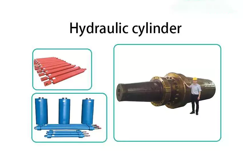
How do hydraulic cylinders handle variations in load and pressure during operation?
Hydraulic cylinders are designed to handle variations in load and pressure during operation, making them versatile and efficient in various applications. Hydraulic systems use the principle of transmitting force through incompressible fluid to generate linear motion. Here’s a detailed explanation of how hydraulic cylinders handle variations in load and pressure:
1. Load Handling:
– Hydraulic cylinders are capable of handling different loads by utilizing the principle of Pascal’s law. According to Pascal’s law, when pressure is applied to a fluid in a confined space, the pressure is transmitted equally in all directions. In a hydraulic cylinder, the force applied to the piston results in an equal force output at the rod end of the cylinder. The size of the piston and the pressure exerted determine the force generated by the cylinder. Therefore, hydraulic cylinders can handle a wide range of loads by adjusting the pressure applied to the fluid.
2. Pressure Compensation:
– Hydraulic systems incorporate pressure compensation mechanisms to handle variations in pressure during operation. Pressure compensating valves or regulators are often used to maintain a consistent pressure in the hydraulic system, regardless of load changes. These valves automatically adjust the flow rate or pressure to ensure stable and controlled operation of the hydraulic cylinder. By compensating for pressure variations, hydraulic cylinders can maintain a consistent force output and prevent damage or instability due to excessive pressure.
3. Control Valves:
– Control valves play a crucial role in managing variations in pressure and load during hydraulic cylinder operation. Directional control valves, such as spool valves or poppet valves, control the flow of hydraulic fluid into and out of the cylinder, enabling precise control of the cylinder’s extension and retraction. By adjusting the position of the control valve, the speed and force exerted by the hydraulic cylinder can be regulated to match the load and pressure requirements of the application. Control valves allow for efficient handling of variations in load and pressure by providing fine-tuned control over the hydraulic system.
4. Accumulators:
– Hydraulic accumulators are often used to handle fluctuations in pressure and load. Accumulators store hydraulic fluid under pressure, which can be released or absorbed as needed to compensate for sudden changes in load or pressure. When the load on the hydraulic cylinder decreases, the accumulator releases stored fluid to maintain pressure and prevent pressure spikes. Conversely, when the load on the cylinder increases, the accumulator absorbs excess fluid to maintain system stability. By utilizing accumulators, hydraulic cylinders can effectively handle variations in load and pressure, ensuring smooth and controlled operation.
5. Feedback and Control Systems:
– Advanced hydraulic systems may incorporate feedback and control systems to monitor and adjust the operation of hydraulic cylinders in real-time. Position sensors or pressure sensors provide feedback on the cylinder’s position, force, and pressure, allowing the control system to make continuous adjustments to optimize performance. These systems can automatically adapt to variations in load and pressure, ensuring precise control and efficient operation of the hydraulic cylinder.
6. Design Considerations:
– Proper design considerations, such as selecting the appropriate cylinder size, piston diameter, and rod diameter, are essential for handling variations in load and pressure. The design should account for the maximum anticipated load and pressure conditions to ensure the hydraulic cylinder operates within its specified range. Additionally, the selection of suitable seals, materials, and components that can withstand the anticipated load and pressure variations is crucial for maintaining the reliability and longevity of the hydraulic cylinder.
By utilizing the principles of hydraulic systems, incorporating pressure compensation mechanisms, employing control valves and accumulators, and implementing feedback and control systems, hydraulic cylinders can effectively handle variations in load and pressure during operation. These features and design considerations allow hydraulic cylinders to adapt and perform optimally in a wide range of applications and operating conditions.


editor by CX 2023-09-13
China OEM Hydraulic Cylinders Used for Coal Mine or Tipper Truck with Great quality
Product Description
Company Information
We are 1 of the biggest hydraulic cylinder manufacturer in China, specialized in design, R & D and manufacturing of hydraulic machinery products etc, with its annual production capaciy of 2 square meters.There are 700 sets of mnufacturing equipment .
Product Description
1. hydraulic telescopic cylinder for coal mining drawing and parameter
2. hydraulic telescopic cylinder for coal mining products showcase
3. hydraulic telescopic cylinder for coal mining produce line
700 sets manufacturing equipment,such as cold drawing production line ,heat treatment production line ,surface treatment production line,testing equipment,various digital-control machining equipment,gantry style linear electroplating production line.
4. hydraulic telescopic cylinder for coal mining quality guarantee system
Program before Delivery
1. Trial Operation Test
2. Start-up Pressure Test
3. Pressure-Tight Test
4. Leak Test
5. Full Stroke Test
6. Buffer Test
7. Testing the Effect of Limit
8. Load Efficiency Test
9. Reliability Test
Every piece of hydraulic cylinder are tested and will send out only after they are pasted the each test.
Our company has abundant technical force and perfect testing means. By making wide technical and business cooperation with many related enterprises, universities, colleges and institutes both at home and abroad, and employing senior engineers and software engineers, we have greatly strengthened and improved our designing, processing, and testing abilities.
5. After-service
1).Pre-sale service: Keep communicating with the truck manufacturers , including selection of product model , design of hydraulic system, test of performance and analysis of the accident. Once the problems occur, we will solve them immediately together with truck manufacturers .
2).The sale service: Provide training and technical support for users.
3).After-sale service: Solve the problem firstly, then analyse responsibility ; Replace the system components immediately if any need.
4). 24 hours telephone service hotline.
6.Exhibition and partner
7. FAQ
Q1: Are you a manufacture or a trade company?
A: Manufacture, we are the leader manufacturer of hydraulic industry in China with over 20 years’ experience and technology accumulation. With strong technical team we could solve any annoyance of you.
Q2: Do you have quality control system?
A: Yes, The quality management system introduced is: ISO/TS 16949:2009-certified by NQA and IATF cert.
Q3: How can i get a booklet and buy a cylinder from you?
A: Very easy! Just leave me a message or email or call me directly, let me know you are interesting in our products. I will talk with you for the details soon!
Q4: Can you tell me the price for the cylinder?
A: 1. Please advice the drawing with technical requirement.
2. Please advice the model No. after you check our booklet.
3. Please advice the tipping capacity, number of stages, closed length, mounting type and size.
4. Please also help advice the quantities, this is very important.
Q5: Do your products come with a warranty?
A: Yes, we have 14month from production time. In this time, if the quality problem we will free repair for you.
Q6: Hydraulic cylinder internal leakage?
A: 3 main reasons causing internal leakage: Overload, polishing bad controlled, cheap seal kits. As is known to all, vehicles in China are often overloaded, our products all designed to bear the overload power. Advanced equipment could assure the polish processing. And we use the imported/TOP brand seals to meet customers’ requirement.
Q7: What about the quality feedback of your products?
A: WE HAVE NEVER RECEIVED EVEN ONCE QUALITY COMPLAINT FOR MANY YEARS OF INTERNATIONAL BUSINESS.
Q8: Can you help me to install or recommend what kind of hydraulic cylinder or power pack should I use for specific machine?
A: Yes, we have 25 experienced engineers who are always ready to help you. If you do not know what kind of hydraulic cylinders should be used in your machine, please just contact us, our engineers will design the exact products match your need.
Q9: What is the delivery time?
A: 20 days for bulk production, which is depend on quality, production process and so on.
Q10: What is your main payment term?
A: T/T, L/C, D/A, D/P either is available.
| Material: | Steel |
|---|---|
| Usage: | Hydraulic Support |
| Structure: | General Cylinder |
| Power: | Hydraulic |
| Standard: | Standard, Nonstandard |
| Pressure Direction: | Single-acting Cylinder |
| Customization: |
Available
|
|
|---|

Can hydraulic cylinders be adapted for specialized applications like material handling?
Yes, hydraulic cylinders can be effectively adapted for specialized applications such as material handling. The versatility, power, and precise control offered by hydraulic cylinders make them well-suited for a wide range of material handling tasks. Hydraulic systems, including cylinders, are commonly used in industrial settings to lift, position, push, pull, and manipulate various types of materials. Here’s a detailed explanation of how hydraulic cylinders can be adapted for specialized material handling applications:
1. Lifting and Lowering:
– Hydraulic cylinders are commonly used for lifting and lowering heavy loads in material handling applications. By utilizing the force generated by hydraulic pressure, cylinders can provide the necessary power to lift and hold loads at different elevations. The precise control offered by hydraulic systems allows for accurate positioning of materials, ensuring efficient and safe lifting operations.
2. Pushing and Pulling:
– Hydraulic cylinders are capable of generating substantial pushing and pulling forces, making them ideal for applications that involve moving or manipulating materials. They can be used to push or pull heavy objects, control the movement of conveyors or rollers, or engage mechanisms for material transfer. The ability to exert high forces with precise control enables hydraulic cylinders to efficiently handle a variety of material handling tasks.
3. Tilting and Rotating:
– Hydraulic cylinders can be adapted to provide tilting and rotating functions in material handling equipment. By integrating cylinders into the design, equipment such as forklifts, cranes, or material handling arms can tilt or rotate to facilitate material placement or maneuvering. Hydraulic cylinders offer the required force and control to achieve smooth and controlled tilting or rotating motions, enhancing operational efficiency in material handling processes.
4. Gripping and Clamping:
– Hydraulic cylinders can be utilized to provide gripping and clamping functions for secure material handling. By incorporating specialized gripping or clamping mechanisms with hydraulic actuation, materials of various shapes and sizes can be securely held or clamped during transportation or processing. Hydraulic cylinders enable precise and adjustable gripping or clamping forces, ensuring the safe and reliable handling of materials.
5. Material Compaction and Forming:
– Hydraulic cylinders can be adapted for material compaction and forming applications. For example, in the production of bricks, hydraulic cylinders are used to apply high pressure and force to compact the raw materials into desired shapes. Similarly, in metal forming processes, hydraulic cylinders are employed to exert force on metal sheets or components, enabling precise shaping and forming operations.
6. Conveyor and Sorting Systems:
– Hydraulic cylinders can be integrated into conveyor and sorting systems to facilitate material movement and sorting. By incorporating hydraulic actuators, conveyor belts or sorting mechanisms can be efficiently controlled for optimal material flow and distribution. Hydraulic cylinders provide the necessary force and control to handle varying load capacities and adjust the speed and position of material transfer, improving the overall efficiency of handling and sorting operations.
7. Customized Designs:
– Hydraulic cylinders can be customized and adapted to meet specific requirements of specialized material handling applications. Engineers can design cylinders with unique dimensions, stroke lengths, mounting options, and sealing arrangements to fit into equipment or systems with specific space limitations or operating conditions. Customized hydraulic cylinders ensure optimal performance and compatibility for specialized material handling tasks.
In summary, hydraulic cylinders can be effectively adapted for specialized material handling applications, offering the necessary force, control, and versatility required in various material handling tasks. Whether it involves lifting and lowering, pushing and pulling, tilting and rotating, gripping and clamping, material compaction and forming, or integration into conveyor and sorting systems, hydraulic cylinders provide reliable and efficient solutions. Their adaptability, precise control, and ability to handle heavy loads make hydraulic cylinders a valuable component in optimizing material handling processes across different industries.
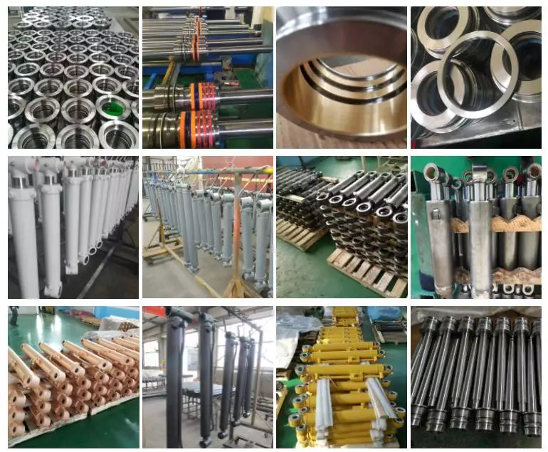
Customization of Hydraulic Cylinders for Marine and Offshore Applications
Yes, hydraulic cylinders can be customized for use in marine and offshore applications. These environments present unique challenges, such as exposure to corrosive saltwater, high humidity, and extreme operating conditions. Customization allows hydraulic cylinders to meet the specific requirements and withstand the harsh conditions encountered in marine and offshore settings. Let’s delve into the details of how hydraulic cylinders can be customized for marine and offshore applications:
- Corrosion Resistance: Marine and offshore environments expose hydraulic cylinders to corrosive elements, such as saltwater. To mitigate corrosion, hydraulic cylinders can be customized with materials and surface treatments that provide enhanced corrosion resistance. For example, cylinders can be constructed from stainless steel or coated with protective layers like chrome plating or specialized coatings to withstand the corrosive effects of saltwater.
- Sealing and Environmental Protection: Hydraulic cylinders for marine and offshore applications require robust sealing systems to prevent water ingress and protect internal components. Customized sealing solutions, such as high-quality seals, wipers, and gaskets, can be employed to ensure effective sealing and resistance to water, debris, and contaminants. Additionally, hydraulic cylinders can be designed with protective features like bellows or boots to shield vulnerable areas from environmental elements.
- High-Pressure and Shock Resistance: Marine and offshore operations may involve high-pressure hydraulic systems and encounters with dynamic loads or shocks. Customized hydraulic cylinders can be engineered to withstand these demanding conditions. They can be designed with reinforced construction, thicker walls, and specialized components to handle high-pressure applications and absorb shock loads, ensuring reliable performance and durability.
- Temperature and Fluid Compatibility: Marine and offshore applications can expose hydraulic cylinders to extreme temperature variations and specific fluid requirements. Customization allows the selection of materials, seals, and fluids compatible with the anticipated temperature range and the specific fluid being used. Hydraulic cylinders can be tailored to maintain optimal performance and reliability under challenging temperature conditions and with the designated fluid type.
- Mounting and Integration: Customized hydraulic cylinders can be designed to facilitate easy integration and mounting within marine and offshore machinery. Mounting options can be tailored to suit the available space and structural requirements of the equipment. Additionally, customized hydraulic cylinder designs can incorporate features for easy maintenance, accessibility, and connection to the hydraulic system, ensuring convenient installation and serviceability in marine and offshore applications.
In summary, hydraulic cylinders can be customized to meet the unique demands of marine and offshore applications. Customization enables the integration of corrosion-resistant materials, robust sealing systems, high-pressure and shock-resistant designs, temperature and fluid compatibility, as well as optimized mounting and integration features. By tailoring hydraulic cylinders to the specific requirements of marine and offshore environments, reliable performance, extended service life, and efficient operation can be achieved in these challenging operating conditions.

Can hydraulic cylinders be customized for specific equipment or attachment needs?
Yes, hydraulic cylinders can be customized to meet specific equipment or attachment needs. Hydraulic cylinder manufacturers often offer customization options to ensure that the cylinders meet the unique requirements of different applications. Here’s a detailed explanation of how hydraulic cylinders can be customized for specific equipment or attachment needs:
1. Size and Configuration:
– Hydraulic cylinders can be customized in terms of size and configuration to fit specific equipment or attachment requirements. The dimensions of the cylinder, such as bore size, rod diameter, and stroke length, can be tailored to match the available space and the desired force or movement requirements. Additionally, the mounting style and orientation of the cylinder can be customized to ensure proper integration with the equipment or attachment.
2. Operating Pressure and Force:
– The operating pressure and force capabilities of hydraulic cylinders can be customized to suit the specific equipment or attachment needs. Different applications may require different force outputs, and hydraulic cylinder manufacturers can design and manufacture cylinders with the appropriate piston area and pressure ratings to meet those requirements. Customization in this aspect ensures optimal performance and efficiency for the particular equipment or attachment.
3. Stroke Length:
– The stroke length of a hydraulic cylinder refers to the distance the piston can travel from fully retracted to fully extended. Customization of the stroke length allows the hydraulic cylinder to accommodate the specific range of motion required by the equipment or attachment. By adjusting the stroke length, the cylinder can be tailored to deliver the necessary extension and retraction capabilities for efficient operation.
4. Mounting Options:
– Hydraulic cylinders can be customized with various mounting options to facilitate easy installation and integration with specific equipment or attachments. Different applications may require different mounting styles, such as flange mounts, trunnion mounts, or clevis mounts. Manufacturers can provide customized mounting options to ensure proper alignment, stability, and functionality when the cylinder is connected to the equipment or attachment.
5. Sealing and Material Options:
– The sealing system of a hydraulic cylinder is crucial for preventing fluid leakage and maintaining the cylinder’s integrity. Hydraulic cylinder manufacturers offer customization options for sealing materials, such as different types of seals and seal configurations, to suit specific equipment or attachment needs. Additionally, customization of cylinder materials, such as selecting corrosion-resistant materials or specialized coatings, can enhance the cylinder’s durability and performance in specific operating environments.
6. Integration with Control Systems:
– In certain applications, hydraulic cylinders may need to be integrated with sophisticated control systems or automation technologies. Customization can involve incorporating sensors, position feedback devices, or other control elements into the hydraulic cylinder design to enable seamless integration with the overall equipment or attachment control system. This customization ensures precise control, monitoring, and synchronization of the hydraulic cylinder’s movements within the specific application.
7. Specialized Features or Accessories:
– Hydraulic cylinder customization can also involve incorporating specialized features or accessories to meet unique equipment or attachment needs. This may include the integration of safety features, such as pressure relief valves or load-holding valves, or the addition of specific ports or fittings for auxiliary functions or attachments. Customization allows hydraulic cylinders to be tailored to the specific requirements and functionalities of the equipment or attachment.
By offering customization options, hydraulic cylinder manufacturers can provide solutions that precisely match the needs of different equipment or attachment applications. Customized hydraulic cylinders ensure optimal performance, efficiency, and integration, enhancing the overall functionality and productivity of the equipment or attachment. It is important to work closely with experienced manufacturers or hydraulic system specialists to determine the specific customization requirements and ensure the successful implementation of customized hydraulic cylinders.


editor by CX 2023-09-13
China Good quality Wp Series Reducer Wpa 60 Worm Gearbox gearbox engine
Product Description
> Product Introduction
Wpw Worm Worm Reductor
1, WP series worm gearbox ‘s the transmission smooth, vibration, shock and noise are small, a large reduction ratio, wide versatility, with all kinds of mechanical equipment.
2, WPA series speed reducer are able to obtain a larger single-stage transmission gear ratio, compact, most models have better gear self-locking, braking requirements for mechanical equipment can save brakes
3, worm thread engagement with the worm gear tooth surface friction loss greater than the gear transmission efficiency and therefore low, easy to heat and higher temperatures.
4, interworking good worm manufactured according to national standards, bearings, seals etc with standard parts. 5,
5, box type basic type (vertical or horizontal box for 2 structures with bottom foot) and the universal type (box is rectangular, multi-faceted with fixed screw, not fitted with bottom foot or the other end foot and other structural type)
6, WP series gear box input shaft coupling methods are the basic type (single input shaft and dual input shaft), 2 motor with flange.
7, WP series reducer ‘ output, position and direction of the input shaft and the input shaft on the next; the output axis and down; the input shaft and down.
8, WP series worm gearbox can be 2 or 3 sets consisting of multi stage gear reducer to get great gear ratio.
| Type: | WP gears reduction gear |
| Model: | WPA40-250 |
| Ratio: | 10,15,20,25,30,40,50,60 |
| Color: | Green,Brown |
| Material: | Cast iron body |
| Worm Gear- Cooper-10-3 # | |
| Worm-20CrMnTi with carburizing and quenching, surface hardness is 56-62HRC | |
| Shaft-chromium steel-45# | |
| Packing: | Paper Carton,Plywood box / per set(With foam board inside) |
| Warranty: | 1 year |
| Input Power: | 0.55kw,0.75kw,1.1kw,1.5kw,2.2kw,4kw,5.5kw,7.5kw |
| Usages: | In industrial machine: Food stuff,Ceramics,chemical, aswell as packing, printing, dyeing,woodworking, glass and plastics….. |
| IEC Flange: | 80B5,90B5,100B5,112B5,132B5…. |
| Lubricant: | Synthetic & Mineral |
> Catalogue
> Our Motor Advantages
1. Reasonable price with excellent quality
2.Each 1 tests carefully
3.Clear nameplate
4.Reliable package
5.High efficiency, smooth runingand low noise
6.Best materials make best performance
> Producing Process
> About Us
HangZhou EXTENSION SPEED ELECTRICITY CO.,LTD (HangZhou GOOD COMMERCE & TRADE CO.LTD) specializes in the sales of all kinds of gearbox , electric motors. On the sales service and management has accumulated rich experience, has a number of highly qualified technical personnel, management norms, quality isstable. Products by the China national mandatory product certification, quality is reliable, reasonable structure,and make “environmental protection” and “energy saving” synchronization.
HangZhou GOOD COMMERCE & TRADE CO.,LTD(GPHQ ) has always been in line with: “based on sincerity, good quality for first, the pursuit of excellence, pioneering and enterprising team, efficient, innovation” . perfect aftersales service; We will set up a business under the bridge of friendship, hand in hand Create brilliant!
FAQ
1, Q:what’s your MOQ for ac gearbox motor ?
A: 1pc is ok for each type electric gear box motor
2, Q: What about your warranty for your induction speed reducer motor ?
A: 1 year ,but except man-made destroyed
3, Q: which payment way you can accept ?
A: TT, western union .
4, Q: how about your payment way ?
A: 100%payment in advanced less $5000 ,30% payment in advanced payment , 70% payment before sending over $5000.
5, Q: how about your packing of speed reduction motor ?
A: plywood case ,if size is small ,we will pack with pallet for less 1 container
6, Q: What information should be given, if I buy electric helical geared motor from you ?
A: rated power, ratio or output speed,type ,voltage , mounting way , quantity , if more is better.
| Application: | Motor, Machinery, Agricultural Machinery |
|---|---|
| Function: | Speed Changing, Speed Reduction |
| Layout: | Bevel |
| Hardness: | Hardened Tooth Surface |
| Installation: | Horizontal Type |
| Step: | Double-Step |
| Customization: |
Available
| Customized Request |
|---|
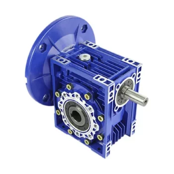
Calculating Gear Ratio in a Worm Reducer
The gear ratio in a worm reducer is determined by the number of teeth on the worm wheel (also known as the worm gear) and the number of threads on the worm shaft. The gear ratio formula for a worm reducer is:
Gear Ratio = Number of Teeth on Worm Wheel / Number of Threads on Worm Shaft
For example, if the worm wheel has 60 teeth and the worm shaft has a single thread, the gear ratio would be 60:1.
It’s important to note that worm reducers have an inherent self-locking property due to the angle of the worm threads. As a result, the gear ratio also affects the mechanical advantage and the system’s ability to resist backdriving.
When calculating the gear ratio, ensure that the worm reducer is properly designed and that the gear ratio aligns with the desired mechanical characteristics for your application. Additionally, consider factors such as efficiency, load capacity, and speed limitations when selecting a gear ratio for a worm reducer.
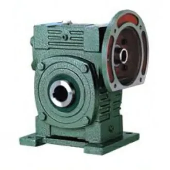
How to Calculate the Efficiency of a Worm Gearbox
Calculating the efficiency of a worm gearbox involves determining the ratio of output power to input power. Efficiency is a measure of how well the gearbox converts input power into useful output power without losses. Here’s how to calculate it:
- Step 1: Measure Input Power: Measure the input power (Pin) using a power meter or other suitable measuring equipment.
- Step 2: Measure Output Power: Measure the output power (Pout) that the gearbox is delivering to the load.
- Step 3: Calculate Efficiency: Calculate the efficiency (η) using the formula: Efficiency (η) = (Output Power / Input Power) * 100%
For example, if the input power is 1000 watts and the output power is 850 watts, the efficiency would be (850 / 1000) * 100% = 85%.
It’s important to note that efficiencies can vary based on factors such as gear design, lubrication, wear, and load conditions. The calculated efficiency provides insight into how effectively the gearbox is converting power, but it’s always a good practice to refer to manufacturer specifications for gearbox efficiency ratings.

What Industries Commonly Use Worm Reducers?
Worm reducers are versatile mechanical components that find applications in various industries due to their unique advantages and capabilities. Some of the industries that commonly use worm reducers include:
- Material Handling: Worm reducers are widely used in material handling equipment such as conveyors, bucket elevators, and cranes to control movement and manage heavy loads.
- Automotive: They are utilized in automotive manufacturing processes, assembly lines, and vehicle positioning systems.
- Food and Beverage: Worm reducers are used in food processing and packaging machinery where hygiene and cleanliness are crucial.
- Agriculture: Agricultural equipment like irrigation systems and tractors use worm reducers for controlling rotational motion.
- Mining and Construction: Heavy-duty applications in mining equipment, excavators, and construction machinery benefit from the torque multiplication provided by worm reducers.
- Energy: Wind turbines and solar tracking systems use worm reducers to convert low-speed, high-torque motion into rotational energy.
- Textile: Textile machinery employs worm reducers for controlling speed and tension in weaving and spinning operations.
- Packaging: Packaging equipment relies on worm reducers for precise movement and positioning of packaging materials.
- Medical: Medical devices and equipment often utilize worm reducers for their accuracy and controlled motion.
- Printing: Printing machines use worm reducers to regulate paper feed and ensure consistent printing quality.
Worm reducers’ ability to provide high torque output, compact design, and self-locking characteristics makes them suitable for applications requiring reliable and controlled motion across various industries.


editor by CX 2023-09-13
China Good quality NMRV050 Worm Gearbox with Output Flange gearbox and motor
Product Description
RV series Characteristics
- RV – Sizes:–150
- Input Options: with input shaft, With Square flange,With Input Flange
- Input Power 0.06 to 11 kW
- RV-Size from 030 to 105 in die-cast aluminium alloy budy and over 110 in cast iron
- Ratios between 5 and 100
- Max torque 1550 N.m and admissible output radial loads max 8771 N
- Aluminium units are supplied complete with synthetic oil and allow for universal mounting positions, with no need to modify lubricant quantity
- Worm wheel: Copper (KK Cu).
- Loading capacity in accordance with: ISO 9001:2015/GB/T 19001-2016
- Size 030 and over are painted with RAL 5571 blue
- Worm gear reducers are available with diffferent combinations: NMRV+NMRV, NMRVpower+NMRV, JWB+NMRV
- NMRV, NRV+VS,NMRV+AS,NMRV+VS,NMRV+F
- Options: torque arm, output flange, viton oil seals, low/high temperature oil, filling/drain/breather/level plug,Small gap
Basic models can be applied to a wide range of power reduction ratios from 5 to 1000.
Warranty: One year from date of delivery.
| WORM GEARBOX | |||||
| SNW SERIES | Output Speed Range: | ||||
| Type | Old Type | Output Torque | Output Shaft Dia. | 14rpm-280rpm | |
| SNW030 | RV030 | 21N.m | φ14 | Applicable Motor Power: | |
| SNW040 | RV040 | 45N.m | φ19 | 0.06kW-11kW | |
| SNW050 | RV050 | 84N.m | φ25 | Input Options1: | |
| SNW063 | RV063 | 160N.m | φ25 | With Inline AC Motor | |
| SNW075 | RV075 | 230N.m | φ28 | Input Options2: | |
| SNW090 | RV090 | 410N.m | φ35 | With Square flange | |
| SNW105 | RV105 | 630N.m | φ42 | Input Options3: | |
| SNW110 | RV110 | 725N.m | φ42 | With Input Shaft | |
| SNW130 | RV130 | 1050N.m | φ45 | Input Options4: | |
| SNW150 | RV150 | 1550N.m | φ50 | With Input Flange |
Starshine Drive
ZheJiang CHINAMFG Drive Co.,Ltd,the predecessor was a state-owned mould enterprise, was established in 1965. CHINAMFG specializes in the complete power transmission solution for high-end equipment manufacturing industries based on the aim of “Platform Product, Application Design and Professional Service”.
Starshine have a strong technical force with over 350 employees at present, including over 30 engineering technicians, 30 quality inspectors, covering an area of 80000 square CHINAMFG and kinds of advanced processing machines and testing equipments. We have a good foundation for the industry application development and service of high-end speed reducers & variators owning to the provincial engineering technology research center,the lab of gear speed reducers, and the base of modern R&D.
Our Team
Quality Control
Quality:Insist on Improvement,Strive for Excellence With the development of equipment manufacturing indurstry,customer never satirsfy with the current quality of our products,on the contrary,wcreate the value of quality.
Quality policy:to enhance the overall level in the field of power transmission
Quality View:Continuous Improvement , pursuit of excellence
Quality Philosophy:Quality creates value
3. Incoming Quality Control
To establish the AQL acceptable level of incoming material control, to provide the material for the whole inspection, sampling, immunity. On the acceptance of qualified products to warehousing, substandard goods to take return, check, rework, rework inspection; responsible for tracking bad, to monitor the supplier to take corrective measures
to prevent recurrence.
4. Process Quality Control
The manufacturing site of the first examination, inspection and final inspection, sampling according to the requirements of some projects, judging the quality change trend;
found abnormal phenomenon of manufacturing, and supervise the production department to improve, eliminate the abnormal phenomenon or state.
5. FQC(Final QC)
After the manufacturing department will complete the product, stand in the customer’s position on the finished product quality verification, in order to ensure the quality of
customer expectations and needs.
6. OQC(Outgoing QC)
After the product sample inspection to determine the qualified, allowing storage, but when the finished product from the warehouse before the formal delivery of the goods, there is a check, this is called the shipment inspection.Check content:In the warehouse storage and transfer status to confirm, while confirming the delivery of the product
is a product inspection to determine the qualified products.
Packing
Delivery
| Application: | Motor, Machinery, Agricultural Machinery |
|---|---|
| Function: | Speed Reduction |
| Layout: | Corner |
| Hardness: | Hardened Tooth Surface |
| Installation: | Vertical Type |
| Step: | Single-Step |
| Customization: |
Available
| Customized Request |
|---|
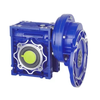
Maintenance Tips for Prolonging the Life of a Worm Gearbox
Proper maintenance is essential to ensure the longevity and reliable performance of a worm gearbox. Here are some maintenance tips to consider:
- Lubrication: Regularly check and replenish the lubricant in the gearbox. Use the recommended lubricant type and quantity specified by the manufacturer.
- Lubrication Schedule: Follow a lubrication schedule based on the operating conditions and manufacturer recommendations. Regular lubrication prevents friction, reduces wear, and dissipates heat.
- Temperature Monitoring: Keep an eye on the operating temperature of the gearbox. Excessive heat can degrade the lubricant and damage components.
- Cleanliness: Keep the gearbox and surrounding area clean from debris and contaminants. Regularly inspect and clean the gearbox exterior.
- Seal Inspection: Check for any leaks or damage to seals and gaskets. Replace them promptly to prevent lubricant leaks and contamination.
- Alignment: Ensure proper alignment between the worm and worm wheel. Misalignment can lead to increased wear and reduced efficiency.
- Torque Monitoring: Monitor the torque levels during operation. Excessive torque can cause overloading and premature wear.
- Regular Inspections: Periodically inspect all components for signs of wear, damage, or unusual noise. Replace worn or damaged parts promptly.
- Proper Usage: Operate the gearbox within its specified limits, including load, speed, and temperature. Avoid overloading or sudden changes in operating conditions.
- Expert Maintenance: If major maintenance or repairs are needed, consult the manufacturer’s guidelines or seek the assistance of qualified technicians.
By following these maintenance tips and adhering to the manufacturer’s recommendations, you can extend the lifespan of your worm gearbox and ensure its optimal performance over time.
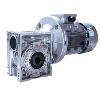
Does a Worm Reducer Require Frequent Maintenance?
Worm reducers generally require less frequent maintenance compared to some other types of gearboxes due to their design and operating characteristics. However, maintenance is still essential to ensure optimal performance and longevity. Here are some key points to consider:
- Lubrication: Proper lubrication is crucial for worm gearboxes. Regularly check the lubricant level and quality to prevent wear and overheating. Lubricant should be changed as recommended by the manufacturer.
- Inspections: Periodically inspect the gearbox for signs of wear, damage, or oil leaks. Check for any unusual noises, vibrations, or changes in performance that could indicate a problem.
- Tightening and Alignment: Check and tighten any loose fasteners and ensure that the gearbox is properly aligned. Misalignment can lead to increased wear and reduced efficiency.
- Seal Maintenance: Inspect and maintain seals to prevent oil leakage and contaminants from entering the gearbox.
- Cleaning: Keep the gearbox clean from debris and contaminants that could affect its performance. Regular cleaning can prevent premature wear and damage.
- Load and Speed: Ensure that the gearbox is operating within its rated load and speed limits. Exceeding these limits can lead to accelerated wear and potential failure.
- Environmental Conditions: Consider the operating environment of the gearbox. Extreme temperatures, humidity, and other factors can impact the gearbox’s performance and longevity.
While worm gearboxes are known for their durability and self-locking feature, neglecting maintenance can lead to premature wear, reduced efficiency, and potential breakdowns. Following the manufacturer’s recommendations for maintenance intervals and procedures is essential to keep the worm reducer in optimal condition.

How to Select the Right Worm Gearbox for Your Application
Selecting the right worm gearbox for your application involves careful consideration of various factors:
- Load Requirements: Determine the torque and load requirements of your application to ensure the selected gearbox can handle the load without compromising performance.
- Speed Reduction: Calculate the required gear reduction ratio to achieve the desired output speed. Worm gearboxes are known for high reduction ratios.
- Efficiency: Consider the gearbox’s efficiency, as worm gearboxes typically have lower efficiency due to the sliding action. Evaluate whether the efficiency meets your application’s needs.
- Space Constraints: Assess the available space for the gearbox. Worm gearboxes have a compact design, making them suitable for applications with limited space.
- Mounting Options: Determine the mounting orientation and configuration that best suits your application.
- Operating Environment: Consider factors such as temperature, humidity, and exposure to contaminants. Choose a gearbox with appropriate seals and materials to withstand the environment.
- Backlash: Evaluate the acceptable level of backlash in your application. Worm gearboxes may exhibit more backlash compared to other gear types.
- Self-Locking: If self-locking capability is required, confirm that the selected gearbox can prevent reverse motion without the need for external braking mechanisms.
- Maintenance: Consider the maintenance requirements of the gearbox. Some worm gearboxes require periodic lubrication and maintenance to ensure proper functioning.
- Cost: Balance the features and performance of the gearbox with the overall cost to ensure it aligns with your budget.
Consult with gearbox manufacturers or experts to get recommendations tailored to your specific application. Testing and simulations can also help validate the suitability of a particular gearbox for your needs.


editor by CX 2023-09-13
China Custom Nmrv Series Aluminum Speed Reducer Durable Service Life Worm Gearbox manufacturer
Product Description
Product Parameters
Editing and broadcasting of main materials
1. Body, die-casting aluminum alloy;
2. Worm shaft, 20 Crq steel, high temperature treatment;
3. Worm gear, nickel bronze alloy;
4. Aluminum alloy body, sandblasting and surface anti-corrosion treatment;
5. Cast iron body, painted with bIu RA5571.
Regular center distance specification editing and broadcasting
Center distance: 130 (unit: mm).
Output hole/shaft diameter: 11, 14, 18, 25, 28, 35, 42, 45 (unit: mm)
Detailed Photos
|
NMRV-063-30-VS–AS-80B5-0.75KW-B3 |
|||
|
NMRV |
Means hole-input with flange |
||
|
NRV |
Means shaft-input without flange |
||
|
063 |
Centre-to-centre spacing of worm-gear speed reducer |
||
|
30 |
ratio |
||
|
VS |
Double input shaft |
F1(FA) |
Flange putput shaft |
|
AS |
Single output shaft |
AB |
Double output shaft |
|
PAM |
|
80B5 |
Motor mounting facility |
|
0.75KW |
|
B3 |
Mounting position |
|
N2 |
NRV571 |
NRV030 |
NRV040 |
NRV050 |
NRV063 |
NRV075 |
NRV090 |
NRV110 |
NRV130 |
|
400 |
390 |
530 |
1571 |
1400 |
1830 |
2160 |
2390 |
3571 |
3950 |
|
250 |
460 |
620 |
1200 |
1650 |
2150 |
2520 |
2800 |
3530 |
4610 |
|
150 |
550 |
740 |
1420 |
1960 |
2450 |
2990 |
3310 |
4180 |
5470 |
|
100 |
630 |
850 |
1620 |
2250 |
2910 |
3430 |
3800 |
4790 |
6260 |
|
60 |
740 |
1000 |
1920 |
2660 |
3450 |
4060 |
4500 |
5680 |
7420 |
|
40 |
850 |
1150 |
2200 |
3050 |
3950 |
4650 |
5150 |
6500 |
8500 |
|
25 |
990 |
1350 |
2570 |
3570 |
4620 |
5440 |
6571 |
7600 |
9940 |
|
10 |
1350 |
1830 |
3490 |
4840 |
6270 |
7380 |
8180 |
10320 |
13500 |
|
|
|
|
|
|
|
|
|
|
|
|
A |
50 |
65 |
84 |
101 |
120 |
131 |
162 |
191 |
203 |
|
B |
38 |
50 |
64 |
76 |
95 |
101 |
122 |
151 |
163 |
Use and safety guarantee
1. Please check and confirm the matching intensity between worm gear reducer and mechanical equipment before use to assure that it is in the safety range of worm gear reducer performance parameters
2. Worm gear reducer has filled with WA460 lubricating oil. Please replace the lubricating oil after the first starting of 400 hours and after then 4000 hours for lubricating oil replacing cycle
3. There should be enough lubrication in worm gear box and keep regular check with the oil level.
4. When installation. please be careful to avoid sharp instruments bruising the oil seals on output shaft to cause leakage
5. Please confirm the rotation direction before mechanical connection. If the rotation direction is not correct, it will possible injury or damage the devices
6. Please set safety covers in rotating position to avoid of injuring
7. Please pay full attention: it is very dangerous if there is off or falling when movin
| Hardness: | Hardened Tooth Surface |
|---|---|
| Installation: | 90 Degree |
| Layout: | Expansion |
| Gear Shape: | Bevel Gear |
| Step: | Single-Step |
| Type: | Gear Reducer |
| Samples: |
US$ 30/Piece
1 Piece(Min.Order) | |
|---|
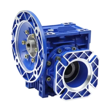
Self-Locking Properties in a Worm Gearbox
Yes, worm gearboxes exhibit self-locking properties, which can be advantageous in certain applications. Self-locking refers to the ability of a mechanism to prevent the transmission of motion from the output shaft back to the input shaft when the system is at rest. Worm gearboxes inherently possess self-locking properties due to the unique design of the worm gear and worm wheel.
The self-locking behavior arises from the angle of the helix on the worm shaft. In a properly designed worm gearbox, the helix angle of the worm is such that it creates a mechanical advantage that resists reverse motion. When the gearbox is not actively driven, the friction between the worm threads and the worm wheel teeth creates a locking effect.
This self-locking feature makes worm gearboxes particularly useful in applications where holding a load in position without external power is necessary. For instance, they are commonly used in situations where there’s a need to prevent a mechanism from backdriving, such as in conveyor systems, hoists, and jacks.
However, it’s important to note that while self-locking properties can be beneficial, they also introduce some challenges. The high friction between the worm gear and worm wheel during self-locking can lead to higher wear and heat generation. Additionally, the self-locking effect can reduce the efficiency of the gearbox when it’s actively transmitting motion.
When considering the use of a worm gearbox for a specific application, it’s crucial to carefully analyze the balance between self-locking capabilities and other performance factors to ensure optimal operation.

Worm Gearbox vs. Helical Gearbox: A Comparison
Worm gearboxes and helical gearboxes are two popular types of gear systems, each with its own set of advantages and disadvantages. Let’s compare them:
| Aspect | Worm Gearbox | Helical Gearbox |
| Efficiency | Lower efficiency due to sliding friction between the worm and worm wheel. | Higher efficiency due to rolling contact between helical gear teeth. |
| Torque Transmission | Excellent torque transmission and high reduction ratios achievable in a single stage. | Good torque transmission, but may require multiple stages for high reduction ratios. |
| Noise and Vibration | Generally higher noise and vibration levels due to sliding action. | Lower noise and vibration levels due to smoother rolling contact. |
| Backlash | Higher inherent backlash due to the design. | Lower backlash due to meshing of helical teeth. |
| Efficiency at Higher Speeds | Less suitable for high-speed applications due to efficiency loss. | More suitable for high-speed applications due to higher efficiency. |
| Overload Protection | Natural self-locking feature provides some overload protection. | May not have the same level of inherent overload protection. |
| Applications | Commonly used for applications requiring high reduction ratios, such as conveyor systems and heavy-duty machinery. | Widely used in various applications including automotive transmissions, industrial machinery, and more. |
Both worm and helical gearboxes have their place in engineering, and the choice between them depends on the specific requirements of the application. Worm gearboxes are preferred for applications with high reduction ratios, while helical gearboxes are chosen for their higher efficiency and smoother operation.
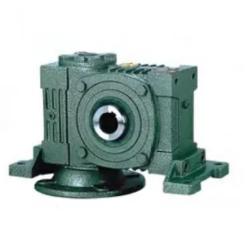
How Does a Worm Gearbox Compare to Other Types of Gearboxes?
Worm gearboxes offer unique advantages and characteristics that set them apart from other types of gearboxes. Here’s a comparison between worm gearboxes and some other common types:
- Helical Gearbox: Worm gearboxes have higher torque multiplication, making them suitable for heavy-load applications, while helical gearboxes are more efficient and offer smoother operation.
- Bevel Gearbox: Worm gearboxes are compact and can transmit motion at right angles, similar to bevel gearboxes, but worm gearboxes have self-locking capabilities.
- Planetary Gearbox: Worm gearboxes provide high torque output and are cost-effective for applications with high reduction ratios, whereas planetary gearboxes offer higher efficiency and can handle higher input speeds.
- Spur Gearbox: Worm gearboxes have better shock load resistance due to their sliding motion, while spur gearboxes are more efficient and suitable for lower torque applications.
- Cycloidal Gearbox: Cycloidal gearboxes have high shock load capacity and compact design, but worm gearboxes are more cost-effective and can handle higher reduction ratios.
While worm gearboxes have advantages such as high torque output, compact design, and self-locking capability, the choice between gearbox types depends on the specific requirements of the application, including torque, efficiency, speed, and space limitations.


editor by CX 2023-09-13
China OEM Nmrv Transmission Worm Gear Reduction Gearbox for Lifting Machinery differential gearbox
Product Description
Product Description
Main Materials:
1)housing:aluminium alloy ADC12(size 571-090); die cast iron HT200(size 110-150);
2)Worm:20Cr, ZI Involute profile; carbonize&quencher heat treatment make gear surface hardness up to 56-62 HRC; After precision grinding, carburization layer’s thickness between 0.3-0.5mm.
3)Worm Wheel:wearable stannum alloy CuSn10-1
Detailed Photos
Combination Options:
Input:with input shaft, With square flange,With IEC standard input flange
Output:with torque arm, output flange, single output shaft, double output shaft, plastic cover
Worm reducers are available with diffferent combinations: NMRV+NMRV, NMRV+NRV, NMRV+PC, NMRV+UDL, NMRV+MOTORS
Exploded View:
Product Parameters
| Old Model |
New Model | Ratio | Center Distance | Power | Input Dia. | Output Dia. | Output Torque | Weight |
| RV571 | 7.5~100 | 25mm | 0.06KW~0.12KW | Φ9 | Φ11 | 21N.m | 0.7kgs | |
| RV030 | RW030 | 7.5~100 | 30mm | 0.06KW~0.25KW | Φ9(Φ11) | Φ14 | 45N.m | 1.2kgs |
| RV040 | RW040 | 7.5~100 | 40mm | 0.09KW~0.55KW | Φ9(Φ11,Φ14) | Φ18(Φ19) | 84N.m | 2.3kgs |
| RV050 | RW050 | 7.5~100 | 50mm | 0.12KW~1.5KW | Φ11(Φ14,Φ19) | Φ25(Φ24) | 160N.m | 3.5kgs |
| RV063 | RW063 | 7.5~100 | 63mm | 0.18KW~2.2KW | Φ14(Φ19,Φ24) | Φ25(Φ28) | 230N.m | 6.2kgs |
| RV075 | RW075 | 7.5~100 | 75mm | 0.25KW~4.0KW | Φ14(Φ19,Φ24,Φ28) | Φ28(Φ35) | 410N.m | 9.0kgs |
| RV090 | RW090 | 7.5~100 | 90mm | 0.37KW~4.0KW | Φ19(Φ24,Φ28) | Φ35(Φ38) | 725N.m | 13.0kgs |
| RV110 | RW110 | 7.5~100 | 110mm | 0.55KW~7.5KW | Φ19(Φ24,Φ28,Φ38) | Φ42 | 1050N.m | 35.0kgs |
| RV130 | RW130 | 7.5~100 | 130mm | 0.75KW~7.5KW | Φ24(Φ28,Φ38) | Φ45 | 1550N.m | 48.0kgs |
| RV150 | RW150 | 7.5~100 | 150mm | 2.2KW~15KW | Φ28(Φ38,Φ42) | Φ50 | 84.0kgs |
GMRV Outline Dimension:
| GMRV | A | B | C | C1 | D(H8) | E(h8) | F | G | G1 | H | H1 | I | M | N | O | P | Q | R | S | T | BL | β | b | t | V |
| 030 | 80 | 97 | 54 | 44 | 14 | 55 | 32 | 56 | 63 | 65 | 29 | 55 | 40 | 57 | 30 | 75 | 44 | 6.5 | 21 | 5.5 | M6*10(n=4) | 0° | 5 | 16.3 | 27 |
| 040 | 100 | 121.5 | 70 | 60 | 18(19) | 60 | 43 | 71 | 78 | 75 | 36.5 | 70 | 50 | 71.5 | 40 | 87 | 55 | 6.5 | 26 | 6.5 | M6*10(n=4) | 45° | 6 | 20.8(21.8) | 35 |
| 050 | 120 | 144 | 80 | 70 | 25(24) | 70 | 49 | 85 | 92 | 85 | 43.5 | 80 | 60 | 84 | 50 | 100 | 64 | 8.5 | 30 | 7 | M8*12(n=4) | 45° | 8 | 28.3(27.3) | 40 |
| 063 | 144 | 174 | 100 | 85 | 25(28) | 80 | 67 | 103 | 112 | 95 | 53 | 95 | 72 | 102 | 63 | 110 | 80 | 8.5 | 36 | 8 | M8*12(n=8) | 45° | 8 | 28.3(31.3) | 50 |
| 075 | 172 | 205 | 120 | 90 | 28(35) | 95 | 72 | 112 | 120 | 115 | 57 | 112.5 | 86 | 119 | 75 | 140 | 93 | 11 | 40 | 10 | M8*14(n=8) | 45° | 8(10) | 31.3(38.3) | 60 |
| 090 | 206 | 238 | 140 | 100 | 35(38) | 110 | 74 | 130 | 140 | 130 | 67 | 129.5 | 103 | 135 | 90 | 160 | 102 | 13 | 45 | 11 | M10*16(n=8) | 45° | 10 | 38.3(41.3) | 70 |
| 110 | 255 | 295 | 170 | 115 | 42 | 130 | – | 144 | 155 | 165 | 74 | 160 | 127.5 | 167.5 | 110 | 200 | 125 | 14 | 50 | 14 | M10*18(n=8) | 45° | 12 | 45.3 | 85 |
| 130 | 293 | 335 | 200 | 120 | 45 | 180 | – | 155 | 170 | 215 | 81 | 179 | 146.5 | 187.5 | 130 | 250 | 140 | 16 | 60 | 15 | M12*20(n=8) | 45° | 14 | 48.8 | 100 |
| 150 | 340 | 400 | 240 | 145 | 50 | 180 | – | 185 | 200 | 215 | 96 | 210 | 170 | 230 | 150 | 250 | 180 | 18 | 72.5 | 18 | M12*22(n=8) | 45° | 14 | 53.8 | 120 |
Company Profile
About CHINAMFG Transmission:
We are a professional reducer manufacturer located in HangZhou, ZHangZhoug province.
Our leading products is full range of RV571-150 worm reducers , also supplied GKM hypoid helical gearbox, GRC inline helical gearbox, PC units, UDL Variators and AC Motors, G3 helical gear motor.
Products are widely used for applications such as: foodstuffs, ceramics, packing, chemicals, pharmacy, plastics, paper-making, construction machinery, metallurgic mine, environmental protection engineering, and all kinds of automatic lines, and assembly lines.
With fast delivery, superior after-sales service, advanced producing facility, our products sell well both at home and abroad. We have exported our reducers to Southeast Asia, Eastern Europe and Middle East and so on.Our aim is to develop and innovate on basis of high quality, and create a good reputation for reducers.
Packing information:Plastic Bags+Cartons+Wooden Cases , or on request
We participate Germany Hannver Exhibition-ZheJiang PTC Fair-Turkey Win Eurasia
Logistics
After Sales Service
1.Maintenance Time and Warranty:Within 1 year after receiving goods.
2.Other Service: Including modeling selection guide, installation guide, and problem resolution guide, etc.
FAQ
1.Q:Can you make as per customer drawing?
A: Yes, we offer customized service for customers accordingly. We can use customer’s nameplate for gearboxes.
2.Q:What is your terms of payment ?
A: 30% deposit before production,balance T/T before delivery.
3.Q:Are you a trading company or manufacturer?
A:We are a manufacurer with advanced equipment and experienced workers.
4.Q:What’s your production capacity?
A:8000-9000 PCS/MONTH
5.Q:Free sample is available or not?
A:Yes, we can supply free sample if customer agree to pay for the courier cost
6.Q:Do you have any certificate?
A:Yes, we have CE certificate and SGS certificate report.
Contact information:
Ms Lingel Pan
For any questions just feel free ton contact me. Many thanks for your kind attention to our company!
| Application: | Motor, Machinery, Marine, Agricultural Machinery, Industry |
|---|---|
| Function: | Distribution Power, Change Drive Torque, Speed Changing, Speed Reduction |
| Layout: | Right Angle |
| Hardness: | Hardened Tooth Surface |
| Installation: | Horizontal Type |
| Step: | Double-Step |
| Samples: |
US$ 12/Piece
1 Piece(Min.Order) | |
|---|
| Customization: |
Available
| Customized Request |
|---|

Can a Worm Gearbox Be Used in Heavy-Duty Machinery?
Yes, a worm gearbox can be used in heavy-duty machinery and is often chosen for such applications due to its inherent characteristics and advantages:
- High Torque Transmission: Worm gearboxes are known for their ability to transmit high torque loads, making them suitable for heavy-duty machinery that requires significant power transmission.
- Load Distribution: The design of worm gears provides robust load distribution and excellent contact between the worm and worm wheel teeth. This enhances their load-carrying capacity, making them capable of handling heavy loads without premature wear or failure.
- Compact Design: Worm gearboxes are compact and offer high reduction ratios in a single stage. This allows for the reduction of high input speeds to lower output speeds, often required in heavy-duty machinery.
- Overload Protection: Worm gears have a natural self-locking feature, which means the gear cannot be easily back-driven by external forces. This feature provides inherent overload protection, preventing damage to the gearbox and machinery in cases of sudden load spikes.
- Smooth Operation: Worm gearboxes offer smooth and steady operation, which is crucial for heavy-duty machinery where precision and controlled movement are essential.
However, when considering the use of a worm gearbox in heavy-duty applications, it’s important to ensure proper engineering and sizing. The design should account for factors such as load, speed, duty cycle, lubrication, and temperature to ensure optimal performance and longevity.
Overall, worm gearboxes are well-suited for heavy-duty machinery across various industries, including mining, construction, manufacturing, and more.
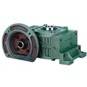
Worm Gearboxes in Conveyor Systems: Benefits and Considerations
Worm gearboxes play a crucial role in conveyor systems, offering several benefits and considerations for their effective integration:
- Space Efficiency: Worm gearboxes have a compact design, making them suitable for applications with limited space, such as conveyor systems.
- High Reduction Ratios: Worm gearboxes can achieve high reduction ratios in a single stage, allowing for slower conveyor speeds without sacrificing torque.
- Self-Locking: Worm gearboxes have inherent self-locking properties, preventing the conveyor from moving when the motor is not actively driving it.
- Directional Control: Worm gearboxes facilitate directional control, enabling the conveyor to move forward or reverse as needed.
- Low Noise: Worm gearboxes often produce lower noise levels compared to other gearbox types, contributing to quieter conveyor operation.
However, there are also considerations to keep in mind when using worm gearboxes in conveyor systems:
- Efficiency: Worm gearboxes may have lower mechanical efficiency compared to some other gearbox types, leading to energy losses.
- Heat Generation: Worm gearboxes can generate more heat due to sliding contact between the worm and gear, necessitating proper cooling mechanisms.
- Lubrication: Proper lubrication is critical to prevent wear and ensure efficient operation. Regular maintenance is required to monitor lubrication levels.
- Load and Speed: Worm gearboxes are well-suited for applications with high torque and low to moderate speed requirements. They may not be optimal for high-speed conveyors.
Before integrating a worm gearbox into a conveyor system, it’s important to carefully consider the specific requirements of the application, including load, speed, space constraints, and efficiency needs. Consulting with gearbox experts and manufacturers can help ensure the right choice for the conveyor’s performance and longevity.

Preventing Backlash in a Worm Gearbox
Backlash in a worm gearbox can lead to reduced accuracy, positioning errors, and decreased overall efficiency. Here are steps to prevent or minimize backlash:
- High-Quality Components: Use high-quality worm gears and worm wheels with tight manufacturing tolerances. Precision components will help reduce backlash.
- Proper Meshing: Ensure the worm gear and worm wheel are properly aligned and meshed. Improper meshing can lead to increased backlash.
- Preload: Applying a small amount of preload to the worm gear can help reduce backlash. However, excessive preload can increase friction and wear.
- Anti-Backlash Mechanisms: Consider using anti-backlash mechanisms, such as spring-loaded systems or adjustable shims, to compensate for any inherent backlash.
- Lubrication: Proper lubrication can reduce friction and play a role in minimizing backlash. Use a lubricant that provides good film strength and reduces wear.
- Maintenance: Regularly inspect and maintain the gearbox to identify and address any changes in backlash over time.
It’s important to strike a balance between reducing backlash and maintaining smooth operation. Consulting with gearbox experts and following manufacturer guidelines will help you optimize your worm gearbox’s performance while minimizing backlash.


editor by CX 2023-09-13
China Best Sales Saf Worm Gearboxes with Hollow Shaft for Extruders with Great quality
Product Description
Product Description
Product Features
High modular design, biomimetic surface with owned intellectual property right.
Adopt German worm hob to process the worm wheel.
With the special gear geometry, it gets high torque, efficiency and long life circle.
It can achieve the direct combination for 2 sets of gearbox.
Mounting mode: foot mounted, flange mounted, torque arm mounted.
Output shaft: CHINAMFG shaft, hollow shaft.
Main applied for
Chemical industry and environmental protection
Metal processing
Building and construction
Agriculture and food
Textile and leather
Forest and paper
Car washing machinery
Detailed Photos
Product Parameters
Technical data:
|
Housing material |
Cast iron/Ductile iron |
|
Housing hardness |
HBS190-240 |
|
Gear material |
20CrMnTi alloy steel |
|
Surface hardness of gears |
HRC58°~62 ° |
|
Gear core hardness |
HRC33~40 |
|
Input / Output shaft material |
42CrMo alloy steel |
|
Input / Output shaft hardness |
HRC25~30 |
|
Machining precision of gears |
accurate grinding, 6~5 Grade |
|
Lubricating oil |
GB L-CKC220-460, Shell Omala220-460 |
|
Heat treatment |
tempering, cementiting, quenching, etc. |
|
Efficiency |
94%~96% (depends on the transmission stage) |
|
Noise (MAX) |
60~68dB |
|
Temp. rise (MAX) |
40°C |
|
Temp. rise (Oil)(MAX) |
50°C |
|
Vibration |
≤20µm |
|
Backlash |
≤20Arcmin |
|
Brand of bearings |
China top brand bearing, HRB/LYC/ZWZ/C&U. Or other brands requested, SKF, FAG, INA, NSK. |
|
Brand of oil seal |
NAK — ZheJiang or other brands requested |
Our Advantages
Certifications
Packaging & Shipping
Company Profile
Xihu (West Lake) Dis.ng Transmission Equipment Co., Ltd. located HangZhou city, ZHangZhoug, as 1 professional manufacturer and exporter of cycloidal pin wheel reducer,worm reducer, gear reducer, gearbox , AC motor and relative spare parts, owns rich experience in this line for many years.
We are 1 direct factory, with advanced production equipment, the strong development team and producing capacity to offer quality products for customers.
Our products widely served to various industries of Metallurgy, Chemicals, lifting,mining,Petroleum,textile,medicine,wooden etc. Main markets: China, Africa,Australia,Vietnam, Turkey,Japan, Korea, Philippines…
Welcome to ask us any questions, good offer always for you for long term business.
FAQ
Q: Are you trading company or manufacturer?
A: We are factory.
Q: How long is your delivery time?
A: Generally it is 5-10 days if the goods are in stock. or it is 15-20 days if the goods are not in stock.
Q: Can we buy 1 pc of each item for quality testing?
A: Yes, we are glad to accept trial order for quality testing.
Q:How to choose a gearbox which meets your requirement?
A:You can refer to our catalogue to choose the gearbox or we can help to choose when you provide
the technical information of required output torque, output speed and motor parameter etc.
Q: What information shall we give before placing a purchase order?
A:a) Type of the gearbox, ratio, input and output type, input flange, mounting position, and motor informationetc.
b) Housing color.
c) Purchase quantity.
d) Other special requirements.
| Application: | Motor, Machinery, Marine, Agricultural Machinery |
|---|---|
| Hardness: | Hardened Tooth Surface |
| Installation: | 90 Degree |
| Layout: | Coaxial |
| Gear Shape: | Worm Gear |
| Step: | Single-Step |

Calculating Gear Ratio in a Worm Reducer
The gear ratio in a worm reducer is determined by the number of teeth on the worm wheel (also known as the worm gear) and the number of threads on the worm shaft. The gear ratio formula for a worm reducer is:
Gear Ratio = Number of Teeth on Worm Wheel / Number of Threads on Worm Shaft
For example, if the worm wheel has 60 teeth and the worm shaft has a single thread, the gear ratio would be 60:1.
It’s important to note that worm reducers have an inherent self-locking property due to the angle of the worm threads. As a result, the gear ratio also affects the mechanical advantage and the system’s ability to resist backdriving.
When calculating the gear ratio, ensure that the worm reducer is properly designed and that the gear ratio aligns with the desired mechanical characteristics for your application. Additionally, consider factors such as efficiency, load capacity, and speed limitations when selecting a gear ratio for a worm reducer.
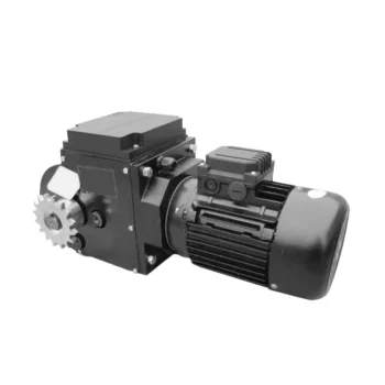
Worm Gearbox Applications in Robotics and Automation
Worm gearboxes play a crucial role in various robotics and automation applications due to their unique characteristics and benefits. Here are some common applications where worm gearboxes are used:
- Robotic Arm Movement: Worm gearboxes are employed in robotic arms to provide precise and controlled movement. The self-locking property of worm gearboxes helps maintain the arm’s position without requiring additional brakes.
- Conveyor Systems: In automated production lines, worm gearboxes are used to drive conveyor belts and move materials or products along assembly lines with accuracy.
- Precision Positioning: Worm gearboxes are used in precision positioning systems, such as those found in pick-and-place robots and CNC machines. They ensure accurate and repeatable movements.
- Pan and Tilt Mechanisms: Worm gearboxes are utilized in pan and tilt mechanisms of surveillance cameras, robotic cameras, and sensors. The self-locking feature helps stabilize and maintain the desired angle.
- Automated Gates and Doors: Worm gearboxes are used in automated gate and door systems to control their opening and closing movements smoothly and safely.
- Material Handling: Robots in warehouses and distribution centers use worm gearboxes to manipulate and lift objects, enhancing efficiency in material handling.
- Medical Robotics: Worm gearboxes are employed in medical robots for surgical procedures, diagnostic equipment, and rehabilitation devices, ensuring precise and controlled movements.
- Industrial Robots: Industrial robots rely on worm gearboxes for various tasks, including welding, painting, assembly, and packaging, where precise movements are essential.
- Automated Testing Equipment: In testing and inspection applications, worm gearboxes provide the necessary movement and positioning for accurate testing and measurements.
- Food and Beverage Industry: Worm gearboxes are used in automated food processing and packaging systems, ensuring hygienic and precise movement of products.
Worm gearboxes are preferred in these applications due to their compact size, high torque output, self-locking feature, and ability to provide a right-angle drive. However, selecting the right gearbox requires considering factors such as load, speed, efficiency, and environmental conditions.

Preventing Backlash in a Worm Gearbox
Backlash in a worm gearbox can lead to reduced accuracy, positioning errors, and decreased overall efficiency. Here are steps to prevent or minimize backlash:
- High-Quality Components: Use high-quality worm gears and worm wheels with tight manufacturing tolerances. Precision components will help reduce backlash.
- Proper Meshing: Ensure the worm gear and worm wheel are properly aligned and meshed. Improper meshing can lead to increased backlash.
- Preload: Applying a small amount of preload to the worm gear can help reduce backlash. However, excessive preload can increase friction and wear.
- Anti-Backlash Mechanisms: Consider using anti-backlash mechanisms, such as spring-loaded systems or adjustable shims, to compensate for any inherent backlash.
- Lubrication: Proper lubrication can reduce friction and play a role in minimizing backlash. Use a lubricant that provides good film strength and reduces wear.
- Maintenance: Regularly inspect and maintain the gearbox to identify and address any changes in backlash over time.
It’s important to strike a balance between reducing backlash and maintaining smooth operation. Consulting with gearbox experts and following manufacturer guidelines will help you optimize your worm gearbox’s performance while minimizing backlash.


editor by CX 2023-09-13